Do you have a question about the Dormakaba Saflok SR Series and is the answer not in the manual?
Details additional hardware needed for routing connections to the mortise.
Requires a 12-24V AC/DC power source with a minimum of 125mA.
Specifies reader proximity to the opening and controller box distance.
Mentions plastic faceplates for optimum transmission and site survey.
Recommends 3 twisted pair x 22 AWG CMP cable for wiring.
Refers to illustrations for required door prep and wire routing.
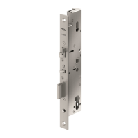
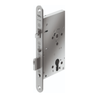
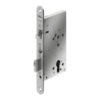
Provides dimensions for the door face view of the mortise and lock installation.
Details dimensions for the door edge view for mortise and lock installation.
Shows dimensional requirements for the door frame view.
Details door frame preparation for Saflok electric mortise locks.
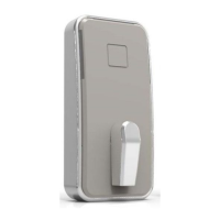
Details SR1 surface mount preparation dimensions and hole specifications.
Shows dimensional requirements for the SR2 flush mount installation.
Provides mounting dimensions for metal, plastic, and SR2 reader single gang boxes.
Provides standalone mounting dimensions for SR2/SR3 for custom integration.
Explains bracket layout and integrator responsibility for custom mounting.
Outlines rules for SR2/SR3 integration to ensure optimum reading performance.
Details environmental factors like RF devices, metal, and water affecting reader performance.
Advises thorough testing with customer credentials and authentic NXP Mifare.
Prepare the door mortise pocket and wire routing tunnel as described previously.
Install power transfer hardware according to manufacturer instructions.
Install mounting brackets, controller boxes, and assemblies using templates.
Verify proper low voltage power is available at the final controller location.
Ensure the controller bracket is properly grounded using the supplied ground wire.
Run wires from SR reader to controller using specified cable, not exceeding 15 meters.
Prepare the mortise for wiring by removing Motor and DAJ connectors.
Run wires from controller to mortise through transfer hardware, not exceeding 15 meters.
Connect wires from the controller to the mortise using the supplied wire nuts.
Verify that all wiring connections are correct.
Install the mortise into the door pocket.
Connect the appropriate power supply to the controller box.
Test the assembly using a construction key.
Program the lock using the property's handheld programmer.
Test the assembly again using a property key.
Secure the faceplate to the controller box with provided screws.
Secure the SR1, SR2, or SR3 reader assembly according to specific instructions.
Retest the lock after all hardware has been securely installed.
Provides a detailed schematic diagram for the SR RFID Reader Concierge Lock.
Illustrates the mortise preparation and SR controller internal parts.
Details two methods for programming the SR RFID Concierge lock.
Lists and illustrates all parts included in the SR Concierge kit.
Details FCC and Industry Canada compliance statements for the device.
| Manufacturer | Dormakaba |
|---|---|
| Mortise | Yes |
| Emergency Key Override | Yes |
| Technology | RFID |
| ADA Compliance | Compliant |
| Power Source | Battery |
| Lock Type | Mortise Lock |
| Holding Force | High |
| Finish Options | Satin Chrome, Bright Brass, Dark Bronze |
| Operating Temperature | -20°C to 70°C (-4°F to 158°F) |