Do you have a question about the Dormakaba DB25K and is the answer not in the manual?
Manual describes installation, connection, operation and maintenance of the lock DB25K.
Identifies installers and service technicians as the target audience for the manual.
Instructs the operator to keep the document for future reference and accessibility.
Outlines the proper applications and suitability of the lock for various door types and environments.
Lists applications and conditions where the lock is not suitable, such as escape routes or humid areas.
Details the operator's responsibilities for proper installation, maintenance, and use of the lock.
Warns that assembly and connection must only be done by qualified persons due to potential danger.
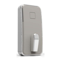
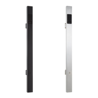
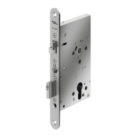
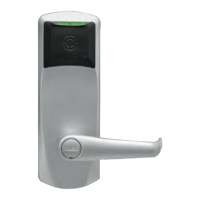
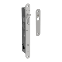
Provides an illustrated view of the lock components with numbered parts for identification.
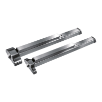
Lists optional accessories available for the lock, including part numbers.
Describes the two available lock variants: Fail-safe (currentless opening) and Fail-secure (closing without power).
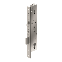
Presents detailed technical specifications including materials, mechanical properties, power supply, and electrical connections.
Displays detailed dimensional drawings of the lock and its associated accessories.
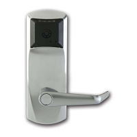
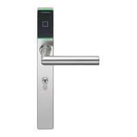
Introduces the lock's features and explains its operation modes, including permanent and short-term unlocking.
Explains how the fail-safe variant operates, including relocking after door closure.
Details the operation of the fail-secure variant, including bolt operation after unlocking.
Details prerequisites for mounting, including product variant, installation type, and position.
Discusses cable routing considerations and provides a table for conductor cross-section selection based on cable length.
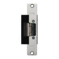
Provides a step-by-step guide with illustrations for installing the lock and strike plate in mortise openings.
Offers a detailed guide with illustrations for mounting the lock on a frame and strike plate on a glass door.
Advises on selecting an appropriate power supply based on the lock's maximum current consumption.
Details the terminal connections for the lock and explains the meaning and remarks for each terminal.
Explains the recommended three-wire connection method for both fail-safe and fail-secure lock variants.
Describes the two-wire connection method, highlighting its limitations compared to the three-wire setup.
Explains how to connect signaling contacts for monitoring door and bolt positions for different lock variants.
Details the use of DIP switches (S1, S2) for configuring the lock's relocking time.
Details the recommended maintenance activities and checks for the lock to ensure proper functioning.
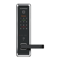
| Access Method | PIN Code, RFID Card, Mechanical Key |
|---|---|
| Material | Zinc Alloy |
| Power Supply | 4 x AA Batteries |
| Emergency Power Supply | 9V Battery |
| Features | Auto-lock |
| Voltage | 6V |
| Operating Temperature | -20°C to 60°C |
| Door Thickness | 35mm - 60mm |