Electrical connection Operating Manual
14 Solenoid Drop Bolt with manual Key Override WN 60425 45532/16458 - 08/2022
6 Electrical connection
6.1 Select power supply
The lock is designed for low power consumption. Only when the deadbolt is moved
does a larger current flow.
1. Select the power supply according to the maximum current consumption.
Note: If several locks are connected to one power supply at the same time, the
maximum current consumptions of the individual locks are added together.
WARNING
In the case of power supplies with high output power, there is a risk of fire due to
high currents in the event of a short circuit!
High currents can cause severe damage due to overheating and even fire.
• In the case of power supplies with high output power, protect the connection
lines to the individual locks with current limiters.
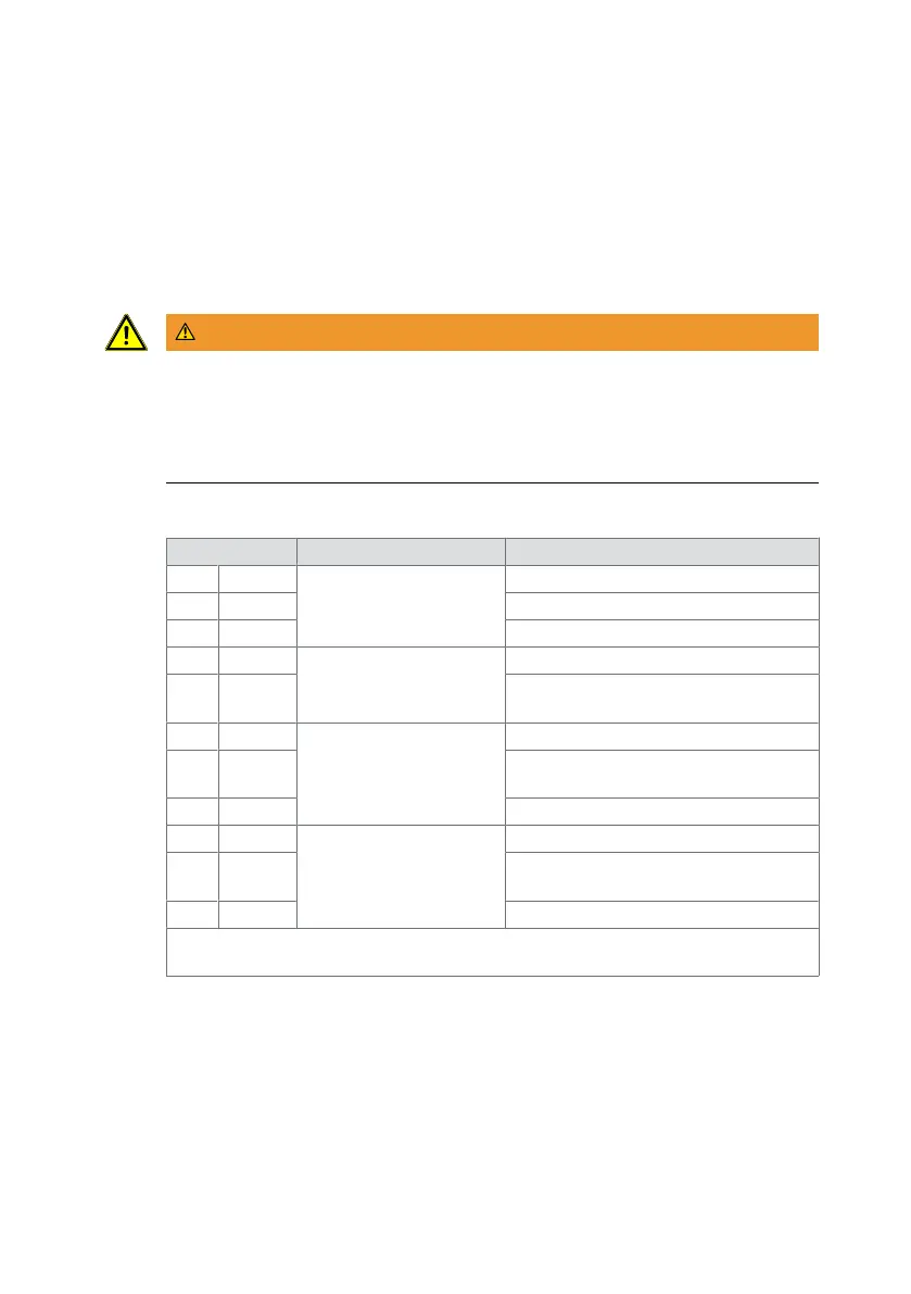
6.2 Connections
Terminal Meaning Remarks
1 + Power supply DC power supply connection, "+".
2 CL Control input
3 - DC power supply connection, "-".
4 C Switch contact door
position
(optional)
Reference potential
5 NO* Normally open contact for door
position
6 C Switch contact bolt
position
(optional)
Reference potential for bolt position
7 NO* Normally open contact for bolt
position
8 NC* NC contact for bolt position
9 C Switching contact key
position
Reference potential for key position
10 NO* Normally open contact for key
position
11 NC* NC contact for key position
*: NO = "normally open", normally open contact. NC = "normally closed", break
contact.
Table3: Connection terminals
For operation, the lock is connected to terminals 1, 2 and 3. If it is not possible or
desired to lay three wires to the lock, the lock can also be connected with only two
wires. Depending on the type of connection, additional wire jumpers may be
required.
Terminals 4 to 11 are signaling contacts that can be evaluated by an access control
or alarm system.