Operating Manual Electrical connection
WN 60425 45532/16458 - 08/2022 Solenoid Drop Bolt with manual Key Override 15
6.3 Three-wire connection (recommended)
In three-wire mode, the power supply is constantly connected to terminals + and -
(terminals 1 and 3). To unlock the lock, control input CL (terminal 2) is supplied
with voltage.
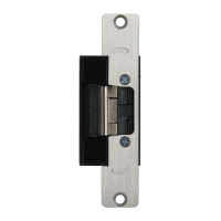
Three-wire connection at fail-safe lock
1. Connect terminals 1 and 9 with a wire jumper.
2. Connect terminals 2 and 11 with a wire jumper.
3. Connect the power supply constantly to
terminals 1 (+) and 3 (-).
4. Connect the control signal for the interlock to
the control input CL (2).
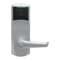
Three-wire connection at fail-secure lock
1. Connect the power supply constantly to
terminals 1 (+) and 3 (-).
2. Connect the control signal for the interlock to
the control input CL (2).
6.4 Two-wire connection
In the two-wire connection, the power supply is connected to terminals +, - and CL
(terminals 1, 2 and 3) via the external switching contact. Unlike the three-wire
connection, the supply voltage is only present when the lock is to unlock.
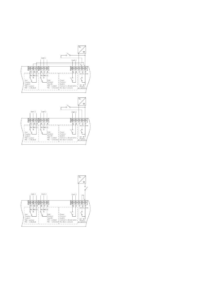
Two-wire connection at fail-safe lock
1. Connect terminals 1 and 2 with a jumper wire.
2. Connect terminal 3 (-) to the negative terminal
of the power supply.
3. Connect the terminal 1 (+) to the switched
positive pole of the power supply.