8Installation
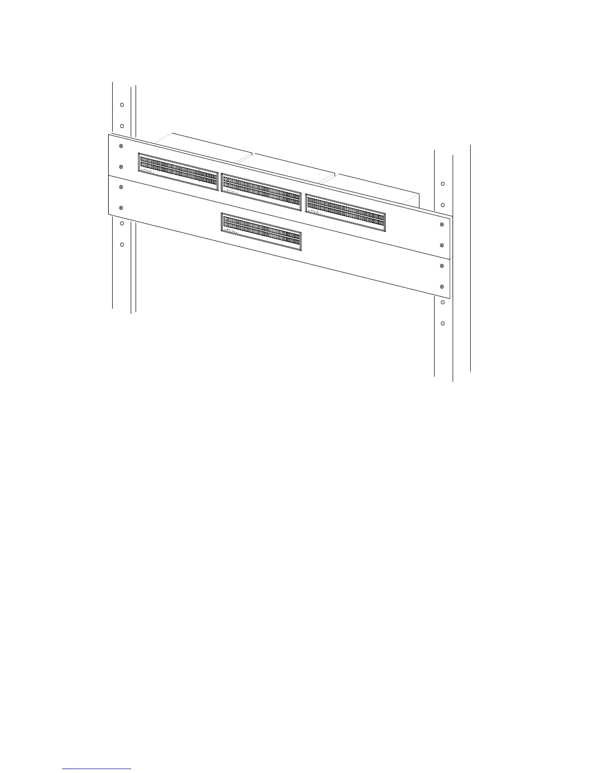
Figure 2-1. Model 280 Rack Mount Adapters
2.4. Electrical
There are three types of electrical connections to the DLM: digital signal
input (and optional output), peak hold function selection, and DC power.
Signal Connection
The DLM is designed to operate with either professional balanced input
lines using a shielded twisted pair, or unbalanced lines using coaxial cable.
Wiring for each is shown in Figure 2-2. Signal connections should be made
to the corresponding terminal of the meter’s Euroconnector.
-57 -54 -51 -48 -45 -42 -39 -36 -33 -30 -29 -28 -27 -26 -25 -24 -23 -22 -21 -20 -19 -18 -17 -16 -15 -14 -13 -12 -11 -10 -9 -8
-7 -6 -5 -4 -3 -2 -1 0
-57 -54 -51 -48 -45 -42 -39 -36 -33 -30 -29 -28 -27 -26 -25 -24 -23 -22 -21 -20 -19 -18 -17 -16 -15 -14 -13 -12 -11 -10 -9 -8
-7 -6 -5 -4 -3 -2 -1 0
MODEL 280-E
U.S.A.
-57 -54 -51 -48 -45 -42 -39 -36 -33 -30 -29 -28 -27 -26 -25 -24 -23 -22 -21 -20 -19 -18 -17 -16 -15 -14 -13 -12 -11 -10 -9 -8
-7 -6 -5 -4 -3 -2 -1 0
-57 -54 -51 -48 -45 -42 -39 -36 -33 -30 -29 -28 -27 -26 -25 -24 -23 -22 -21 -20 -19 -18 -17 -16 -15 -14 -13 -12 -11 -10 -9 -8
-7 -6 -5 -4 -3 -2 -1 0
MODEL 280-E
U.S.A.