Pag
3
di
4
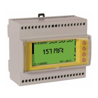
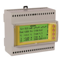
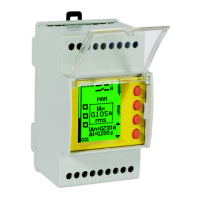
Introduction: The residual current devices, type A/AC Dossena DER3 series, fully compliant with IEC 60947-2: 2019, can be used in LV network in AC, TT and TN type.
The series offers a wide range of adjustment of the I∆n threshold (up to 30 A) and of the delay time (up to 15 sec). DER3 guarantees ease of use, reliability, and speed
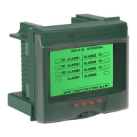
of programming. The measures and parameters are clearly displayed. The variation of the background colour immediately indicates the instrument’s operating status
(Green = residual current protection active, Blue = setup, Red = Alarm / Intervention).
INSTALLATION SUGGESTIONS AND SAFETY PRECAUTION:
All installation and maintenance operations must be carried out by qualified personnel in the absence of voltage and in a total electrical safety regime, in compliance
with the safety regulations.
1) Before powering the DER3, check that all connections have been executed properly.
2) ALWAYS install DER3 combined with Dossena toroidal transducer D series.
3) The cross-section of the conductors must be such that the total resistance of each DER3 ↔transducer connection is less than 0.5Ω.
4) Minimize the distance connections between DER3 and transducer and keep them away from power cables; use twisted shielded cables with the shield connected
to ground at one point only (keep the measurement circuit separate from test circuit).
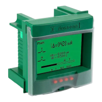
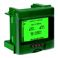
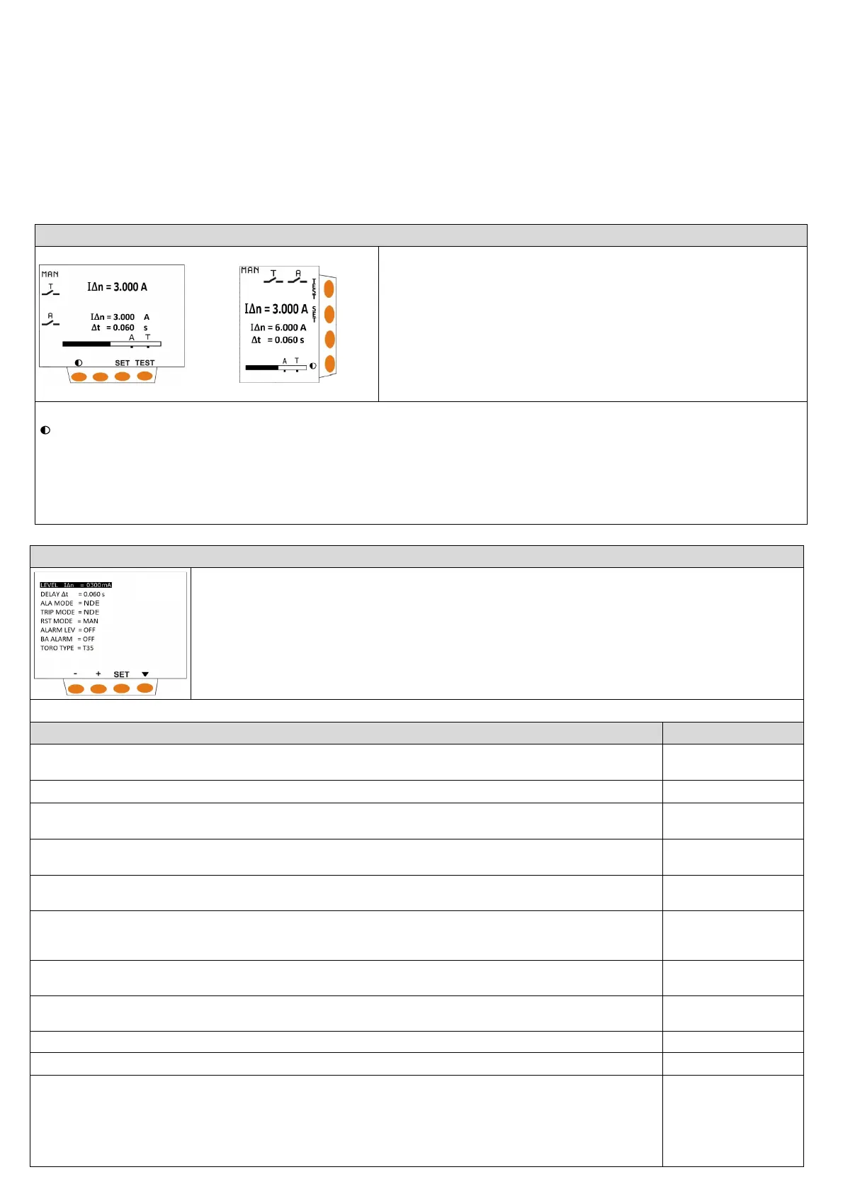
NORMAL VIGILANCE (GREEN DISPLAY)
I∆: Display in true rms value (TRMS) of the residual current in A.
I∆n:
Set threshold of the nominal residual current.
∆t= Set the limiting non-actuating time.
Histogram: represents the measurement of the residual current of the system in % of I∆n
(only for models DER3/2D - 2I - 2IM).
A= graphic visualization of the set alarm threshold (only for models DER3/2D - 2I - 2IM).
T= graphic visualization of the set TRIP threshold.
Keys function:
= press this button to adjust the contrast
SET = press for at least 3 seconds to enter in SET UP.
TEST = press to perform DER3 test.
The test checks the complete protection system (DER3+ toroid series D + T.C.). Push test button to start the test. Display becomes red. The TRIP relay and the 2
nd
relay change state. The writings TESTING - TEST OK - TRIP will appear flashing in series in case of TEST performed correctly. If the reset is set to manual (MAN), press
the RESET key to reset the differential relay. If the test is not performed correctly, the message TEST KO will appear.
RST = reset button, active only in the manual reset mode.
SETUP (BLU DISPLAY)
SET press SET button for at least 3 seconds to enter in SET UP (display becomes blue).
▼ press to switch from one parameter to another in a cyclic way.
+/- press to modify the selected parameter.
press SET button for at least 3 seconds to exit from SETUP and save the parameters.
DER3 automatically exits from SETUP without saving modification, after 3 minutes of inactivity.
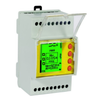
NOTE: in the modular versions the setup items appear sequentially one at a time.
rameters will be operative on
PARAMETERS RANGE
[DEFAULT]
LEVEL IΔn (A)= Threshold of the nominal residual current. The intervention of the TRIP relay will occur when 85% of the set IΔn value is
exceeded.
0,03 ÷ 30A [0,03A]
S
ALA MODE= It represents the rest state of the alarm relay. It is normally open (NDE) and closes in the presence of alarms. In case of NE
the relative contact will become blackened.
NDE/NE [NDE]
TRIP MODE= It represents the rest state of the TRIP relay. It is normally open (NDE) and closes when the IΔ exceeds the IΔn. In case of
the relative contact will become blackened.
NDE/NE [NDE]
" and will therefore allow the
MAN/AUTO [MAN]
ALARM LEVEL= Alarm threshold. When this threshold is exceeded, an alarm condition is generated. If you want to disable this
parameter, set OFF by holding down the key -. If you want the 2nd relay to work as a second trip relay (T), set TT by keeping the key +
OFF/15mA÷85% IΔn/TT
[OFF]
BA ALARM= If set to ON, the continuity of the opening coil and its power supply are constantly monitored, generating an alarm in the
event of an anomaly. In case of 24V Trip Coil set parameter BA Alarm = OFF
ON/OFF [ON]
TORO TYPE= Toroidal transducer choice (T35 - T60 - T80 - T110 - T160 - T210 – T80S (adder toroid tranformation ratio CTs ≤ 500/5) –
T35 ÷ TDRT [T35]
ersions equipped with serial output R
BAUDRATE = Serial speed configuration and parity bit (N= none, E= even, O=odd) (only for versions equipped with serial output RS485).
4800 ÷ 38400 [19200
N]
PSW= To set the password, enter the chosen number in the relevant field. Press the SET button for 3 seconds to exit the setup and save
the setting. From this moment on, every time you enter setup it will be possible to view the operating parameters but it will not be
possible to modify them in any way (not even from serial writings for models that are equipped with them). Instead of the arrow keys,
either a padlock (modular version) or the wording “LOC” (front-panel version) will be displayed.
To disable the password, enter setup and enter the chosen number in the PSW field, allowing you to change the parameters. From this
moment the device will be without a password.
(OFF)/0001 ÷ 9998
[OFF]
 Loading...