* RZN 4308-E = T 2 A
RZN 4316-E = T 2,5 A
RZN 4332-E = T 6,3 A
RZN 4364-E = T 10 A
*
4/16
RZN 43xx-E
99.821.70 3.5/01/12
230 V, 50 Hz
Seperate electric circuit.
Mark fuses.
to further ones
see line lenghts and cross sections
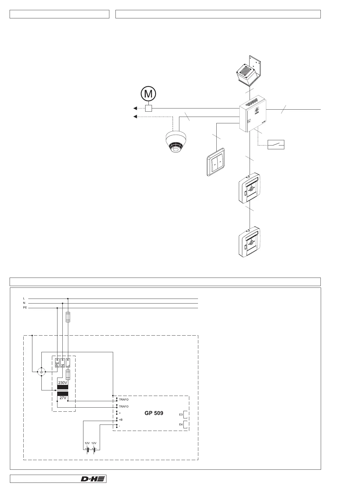
Drive at smoke
vent opening
SHEV control panel
vent button
ca. 1,2 m above
upper edge
firm flooring
smoke vent button
ca. 1,5 m above
upper edge
firm flooring
external control
fire detector
FO 1362 or FT 1262
4x 0,8 Ø
8x 0,8 Ø (RT 45)
10x 0,8 Ø (RT 45-LT)
8x 0,8 Ø (RT 45)
10x 0,8 Ø (RT 45-LT)
2x 0,8 Ø
2x 0,8 Ø
O
K
O
K
rain sensor
4x 0,8 Ø
3x 1,5 mm²
Wiring plan (Paragon)
System voltage 24 V!
Do not run cables with together power lines!
In case of a cable with (green / yellow)
this must !
Cable and terminal boxes have to be labeled.
ground wire
not be used
Slot E1 / E2
AM 44-Z Alarm-cutoff module
TR 42 Cutoff relay module
WFR 41 Weather-stepping-relay
Slot LE
IM 44-E Impulse module
UM 41-Z Transmission module
for sirens, fire bells and flashing lights
for remote indication of fault or alarm
for connecting of several D+H smoke
vent control panels on a wind/ rain
detector
Triggering of alarmand reset from BMS
or series connected smoke vent system
for RT42-Z
Slot GE
AT 41 Drive starting time-lag module
in conjunction with shading systems
Optional Functional Extensions
Connection 230 V
Plan separate electric circuit.
Mark fuses.
Connecting cable: NYM-I 3x1.5
Connected load: RZN 4308E = 240 VA,
RZN 4316E = 500 VA,
RZN 4332E=1kVA,
RZN 4364E=2kVA.
 Loading...