RZN 43xx-E
9/16
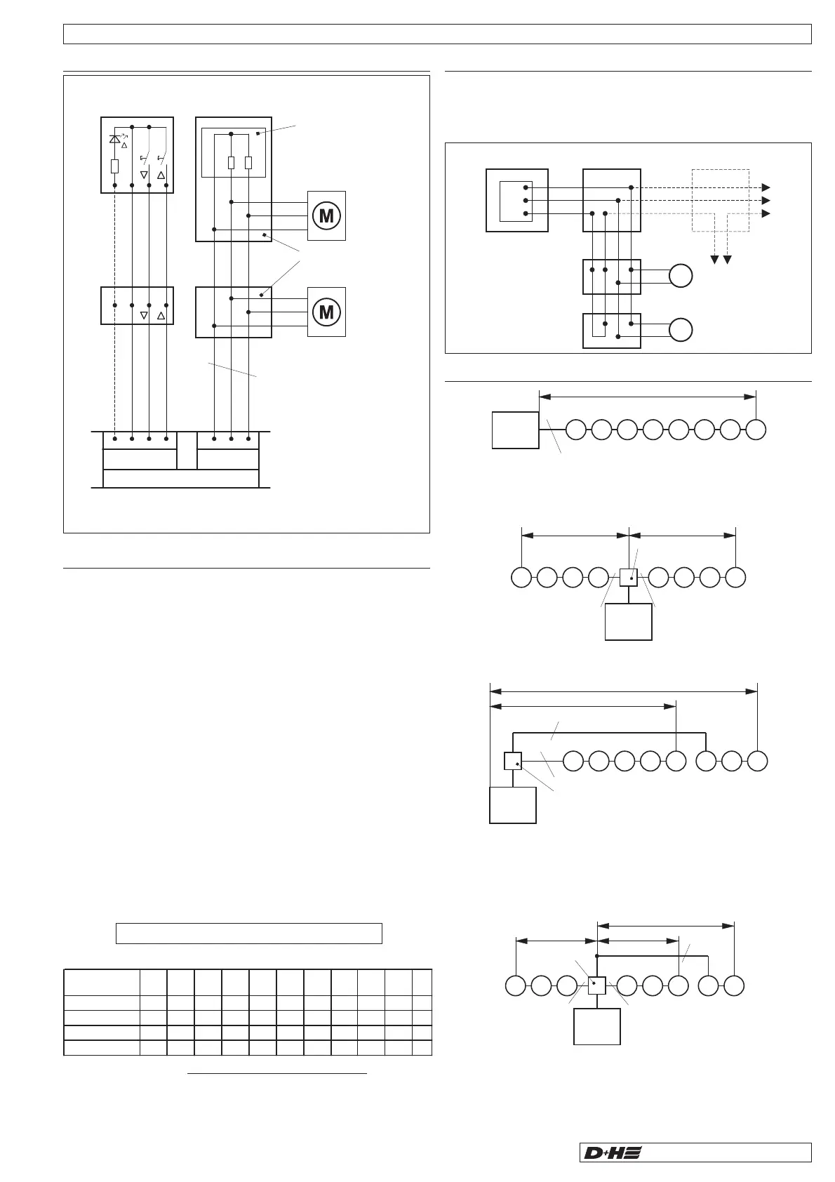
Connection GE 628 (-L) V2
- Supply wires
and branch off parallel
- is looped through
all the cables up to the group end.
Mot. a Mot. b
Monitoring
Connection in case of line branch (GE 628 (-L) V2)
The smoke vent control panel is designed for opening smoke vent devices,
which operate by thermal lifting and through automatic fire recognition
devices (thermal detector, smoke detector). They are triggered either
automatically or manually by smoke detectors at an early stage of a fire and
remain in an opened position without further power consumption. In such a
case, the functional retention of the electrical system is only required at the
early stage of fire. Secured wiring with protection against mechanical
damage is required in accordance with DIN 18232 Part 2.7.2.4.
Cable from the Smoke and heat vent control panel to connect the drive.
Drive lines have a monitoring wire in which fire recognition devices (thermal
maximal detector e.g. THE) can be looped-in:
- standard guidelines for line systems MLAR or safety line with function
retention ... E30, installed in accordance with DIN 4102*.
An increased cable function retention time may be required when drive lines
are installed through areas of the building which are not monitored.
- standard guidelines for line systems MLAR or safety line with function
retention ... E90 installed in accordance with DIN 4102*.
Control cable (Group):
Cables through non-monitored areas:
* Please note: No type designation is given for these cables because of a
large variety on the market. Please consult your D+H distributor about
these.
! The earth conductor must not be wired !
cross section (mm²) =
80
* Connect in parallel 2 wires for each drive line.
** Connect in parallel 3 wires for each drive line.
simple cable length (m) x total current
total
consumption 12345678910A
3x1,5 mm² 120 60 40 30 24 20 17 15 13 12 m
3x2,5 mm² 2001006550403328252220m
*5x2,5 mm² 400200130100806556504440m
**7x 2,5 mm² 600 300 200 150 120 100 85 75 67 60 m
Cable for GE 628 (-L) V2
Connection examples (GE 628 (-L) V2)
control
panel
M
25m
3 x 2,5²
MMMMMMM
Example 1:
1 line
Simple wiring, however unfavourable for voltage drop:
All drives on one cable.
Example 2:
2 lines
Control panel in the centre, one side wired as branch, the other one as
terminal line. 4 wires are required for each branch!
Example 3:
2 lines on one side
Branch and terminal line in same direction.
Number of drives varies in accordance with lengths of lines. 4 wires are
required for each branch!
Example 4:
3 lines
Three cable runs are provided because of the very long distances:
2 cable runs with 3 drives each over 65 m line as branch and 1 cable run with
2 drives over 200 m line. 4 wires are required for each branch.
Group plug-in card GE 628 (-L) V2 ( )continuation
M
50m
3 x 2,5²
4 x 2,5²
branch box
50m
MMM MMMM
control
panel
M
control
panel
65m
40m
4 x 2,5²
3 x 2,5²
MMMM MMM
branch box
M
65m 65m
200m
4 x 2,5²
4 x 2,5²
5 x 2,5²
MMMMMMM
control
panel
branch box
control panel
Mot. b
76
5
Mot. a
monitored
Mot. a
Mot. b
Mot. a
Mot. b
branch box
on motor
branch boxbranch box
branch box
on motor
switch further
branchings
alike
Vent button drives*
LT 43 (-SD)
EM 47 K
terminal module
lenght of line and cross
sections, see page 9
close
–N
OPEN signal
open
close
OPEN signal (only -SD)
–N
open
monitoring
Mot.a
Mot.b
5671234
LT MOT
LP
GE
black
black
orange
2x47kW
branch
box by customer
first to
penultimate
drive
LT 43
LP
Mot. b
-HS*
Mot. a
* For detailed information concerning the connection,
please refer to the instruction for use of respective drive.
last
drive
Mot. b
-HS*
Mot. a
 Loading...