CONTACT US AT www.DRpower.com 15
Figure 20
Negative
Battery
Cable
Battery
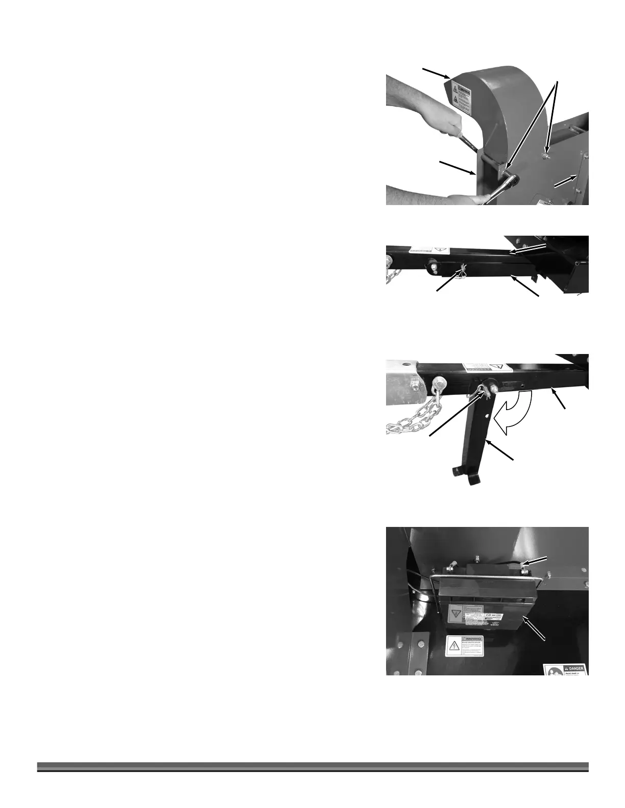
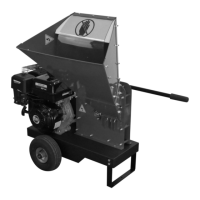
Attaching the Discharge Chute
Tools Needed:
Two 1/2" Wrenches
1. Position the Discharge Chute facing away from the Hopper as shown and
secure with two 4-1/2" long 5/16-18 Bolts, Washers (one Washer on Bolt
side and one on Locknut side) and Locknuts using two 1/2" Wrenches
(Figure 17).
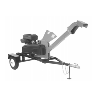
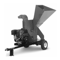
Positioning the Support Leg from Towing to Operating Position
1. Pull the Hitch Clip from the Pin and pull the Pin from the Support Leg and
Tow Bar (Figure 18).
2. Rotate the Support Leg to the down (operating) position, align the holes in
the Tow Bar and Leg, reinstall the Pin and secure with the Hitch Clip (Figure
19).
Connecting the Battery Cable (Electric Start)
We ship the electric-start DR SELF-FEEDING CHIPPER with the negative
terminal battery cable disconnected. This prevents the battery from discharging
during shipment. Before using your electric start DR SELF-FEEDING CHIPPER,
you must connect the battery cable.
Tools Needed:
5/16" Wrench
Phillips Head Screwdriver
1. Connect the Negative Battery Cable onto the Negative Terminal Lug of the
Battery with the existing Bolt, Washer and Nut using a 5/16" Wrench and a
Phillips Head Screwdriver (Figure 20).
Discharge
Chute
Bolts
Washer
and Locknut
Hopper
Figure 17
Chipper
Housing
Tow Bar
Figure 19
Support Leg
Pin w/Hitch
Clip
Figure 18
Support Leg
Pin w/Hitch
Clip
Tow Bar