CONTACT US AT www.DRpower.com 41
OPERATION
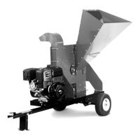
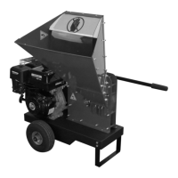
Adjusting the Extended Top-Discharge Chute Discharge Direction:
1. Pull the Hitch Clip and remove the Locking Pin (Figure 67).
2. Rotate the Extended Top-Discharge Chute to the direction desired.
Note: The Extended Top-Discharge Chute has a range of motion of 180˚ that spans
the front and both sides of the Chipper. There are 11 different hole settings at
18˚ increments that you can use.
3. Line up the Locking Pin hole to the closest hole setting in the Discharge
Ring.
4. Install the Locking Pin and secure it with the Hitch Clip.
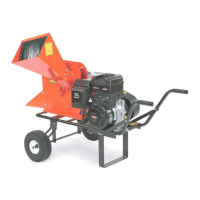
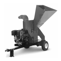
Adjusting the Deflector Direction:
1. Grab the Deflector Handle and rotate the Deflector to the desired discharge
position (Figure 68).
Note: The deflector bolt should be snug, but still allow the deflector to be re-
positioned. Adjust the Bolt tightness if necessary.
MAINTENANCE
Tools and Supplies Needed:
All Purpose Grease
Lubricating the Extended Top-Discharge Chute:
1. Pull the Hitch Clip and remove the Locking Pin from the Discharge Ring
(Figure 67).
2. Apply some all-purpose grease in each hole of the Discharge Ring and
Center Ring as you rotate the Chute.
3. Rotate the Extended Top-Discharge Chute for the full 180˚ of rotation for a
few times to spread the grease inside the Discharge Ring.
4. Reposition the Extended Top-Discharge Chute to the desired angle and
insert the Locking Pin and Hitch Clip.
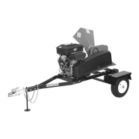
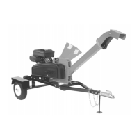
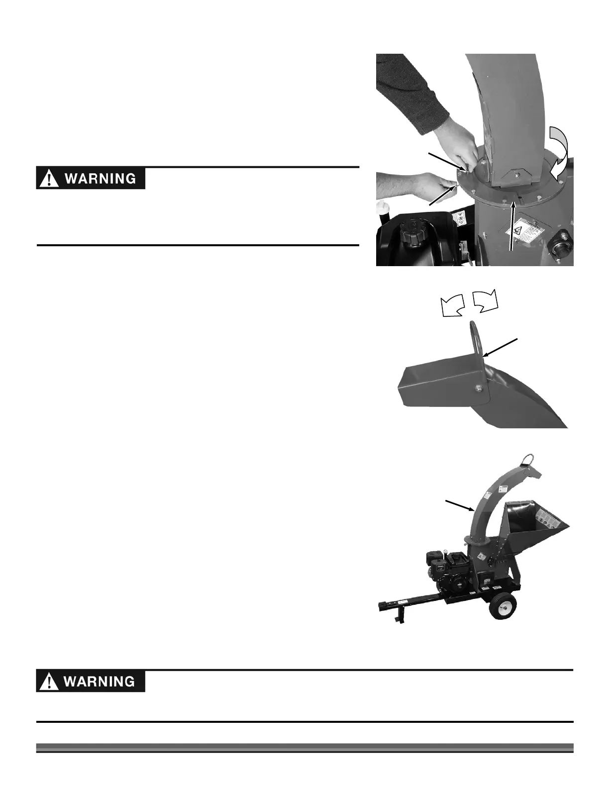
TOWING
1. Pull the Hitch Clip and remove the Locking Pin (Figure 69).
2. Rotate the Extended Top-Discharge Chute so it is pointed towards the back
of the machine.
3. Line up the Locking Pin hole to the closest hole setting in the Discharge
Ring.
4. Install the Locking Pin and secure it with the Hitch Clip.
Locking Pin
Figure 67
Hitch Clip
Extended
Top-Discharge
Chute
Discharge Ring
180°
Deflector
Figure 68
Deflector
Handle
Higher
Discharge
Lower
Discharge
When properly installed, it is not possible to point the Extended Top-
Discharge toward the operator position. Confirm that the 180° range of
motion is away from the operator zone. Contact us at www.DRpower.com or
call 1(800) DR-OWNER (376-9637) if you need assistance.
Extended Top
Discharge Chute
(Towing Position)
Figure 69
For towing safety, the Extended Top Discharge Chute must be positioned towards the back of the machine. Never tow with it
positioned to the side.
 Loading...