CONTACT US AT www.DRpower.com 21
6. For extra safety and security, you may want to purchase a Lock or Lock Pin
to install into the Latch Assembly of the Tow-Hitch Package (Figure 33).
7. Connect the Wire Harness Connector to your Tow Vehicle and ensure that
your lights on the Chipper are working properly.
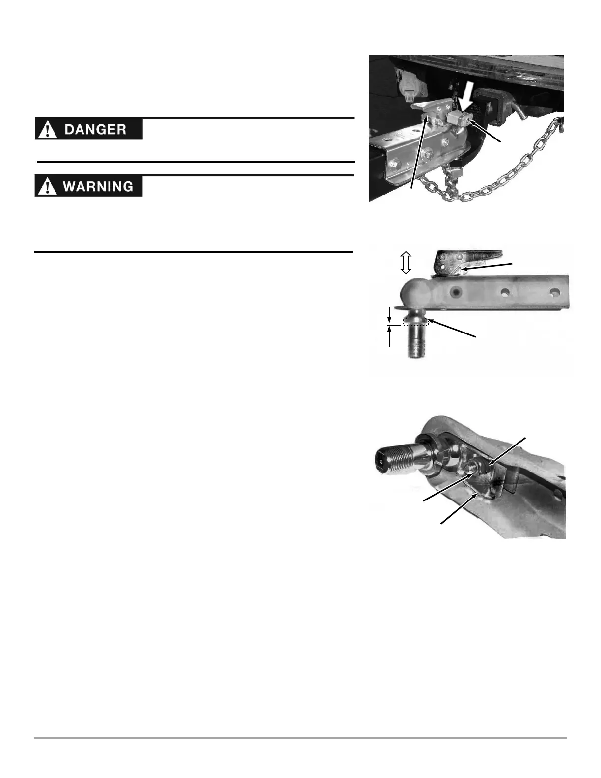
Hitch Coupler Adjustment Check
1. Place the proper size ball in the socket of the coupler and close the latch
assembly (Figure 34). Verify that the locking trigger is properly engaged in
its detent.
2. Pull on the ball and/or coupler, trying to remove the ball from the socket. If
the ball moves more than 1/16" in the coupler’s socket, the clamp requires
adjustment. Follow the proper adjustment procedure in the following
steps.
Hitch Coupler Adjustment
1. With the proper size ball in the socket of the hitch coupler, close the latch
of the coupler completely (Figure 35). Verify that the locking trigger is
properly engaged in its detent.
2. Tighten the lock nut on the underside of the coupler until the spring
between the nut and the clamp is fully compressed. Then back off the lock
nut 1/2 turn or just enough that the latch is able to clamp and unclamp
from the ball.
Making sure the chipper is securely attached to the vehicle is the
responsibility of the owner/operator. Failure to securely attach the chipper can
cause loss of control of the vehicle or the chipper being separated from the
towing vehicle, resulting in serious injury or death.