CONTACT US AT www.DRpower.com 29
Removing and Replacing the Chipper Knife
Tools Needed:
• 7/16" Wrench
• 1/2" Socket with extension
• 3/16" Allen wrench
• Awl or Sharp Tool
• Gloves
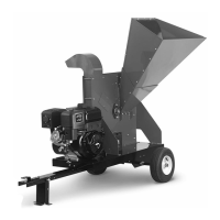
1. Loosen the Locknuts that secure the rear Access Cover (Figure 51). Move
the Cover over to align the larger portion of the hole with the Locknuts and
remove the Cover.
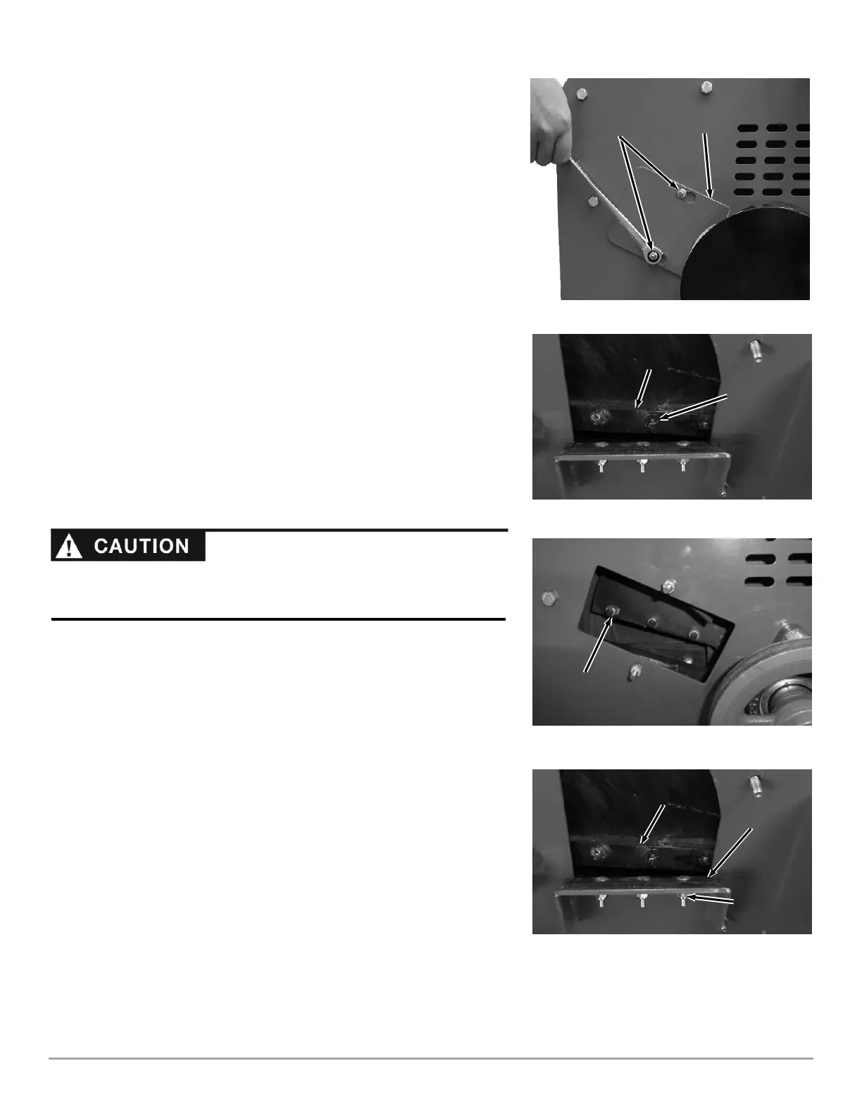
2. Rotate the Flywheel using a stick until the three countersunk Allen Screws
(Figure 52) and Locknuts (Figure 53) attaching the Knife to the Flywheel are
visible through the Access Openings.
3. Clean out the heads of the Allen Screws with an Awl or Sharp Tool (Figure
52).
4. Insert a 3/16” Allen Wrench into the head of a screw.
5. While holding the Allen Wrench, remove the Locknut using a 1/2" socket
(Figure 53).
6. Repeat Steps 5 and 6 for the remaining two Allen Screws.
7. Remove the dull or damaged Knife and visually inspect the Flywheel Slot
and Knife mounting area and be sure they are clean and that the
replacement Knife will be able to mount flush against the Flywheel.
8. Install a new or sharpened Knife as shown with the Knife edge facing down
and towards you (Figure 52) and finger tighten the Allen screws and Lock
Nuts (use the new hardware supplied with a new Knife kit) to hold the Knife
to the Flywheel.
9. Using a 3/16" Allen wrench and a 1/2" socket with extension, tighten the
center Screw and Locknut, then tighten the outer Screw and Locknut, and
finally tighten the inner Screw and Locknut.
10. Double-check that all three Locknuts on the Allen Screws are tight.
11. Check and if needed adjust the gap between the Knife and Wear Plate (See
“Checking and Adjusting the Knife to Wear Plate Gap” in this Chapter).
Removing and Replacing the Wear Plate
Tools Needed:
• 7/16" Wrench
1. Remove the three Locknuts and Carriage Bolts that attach the Wear Plate to
the Chipper Assembly and then remove the Wear Plate (Figure 54).
2. Install the new Wear Plate and secure with the three Carriage Bolts and
Locknuts.
3. Check the Chipper Knife to Wear Plate gap (see that section in this chapter).
 Loading...