• Do not tamper with the engine’s governor setting. The governor controls the maximum safe operation speed and protects
the engine. Over-speeding the engine is dangerous and will cause damage to the engine and to the other moving parts of the
machine. See your authorized dealer for any engine governor adjustments.
• Become familiar with successful operating conditions and avoid those that can overload and damage the machine.
• Do not overload or attempt to chip material beyond manufacturers recommendation. Personal injury or damage to the
machine could result. Learn to recognize the sound of the machine during an overload condition. Only your operator
experience will tell you how fast you can successfully feed material into the machine.
• If overloading or any other cause jams the machine, stop the machine immediately. If you jam the machine and do not stop
the engine, it can burn the drive belt and/or ruin the clutch. Clutch damage can be costly and it may not be covered under
warranty. For this reason, it is important that you immediately shut off the machine if it becomes jammed.
• The centrifugal clutch on this machine is permanently lubricated and does not require oil or grease. If, after long periods of
use, the drum wobbles excessively, replace the clutch assembly. Always replace shoes and springs in sets. Whenever shoes
are changed, replace all springs.
4. Remove the Tire and replace it with a new wheel assembly.
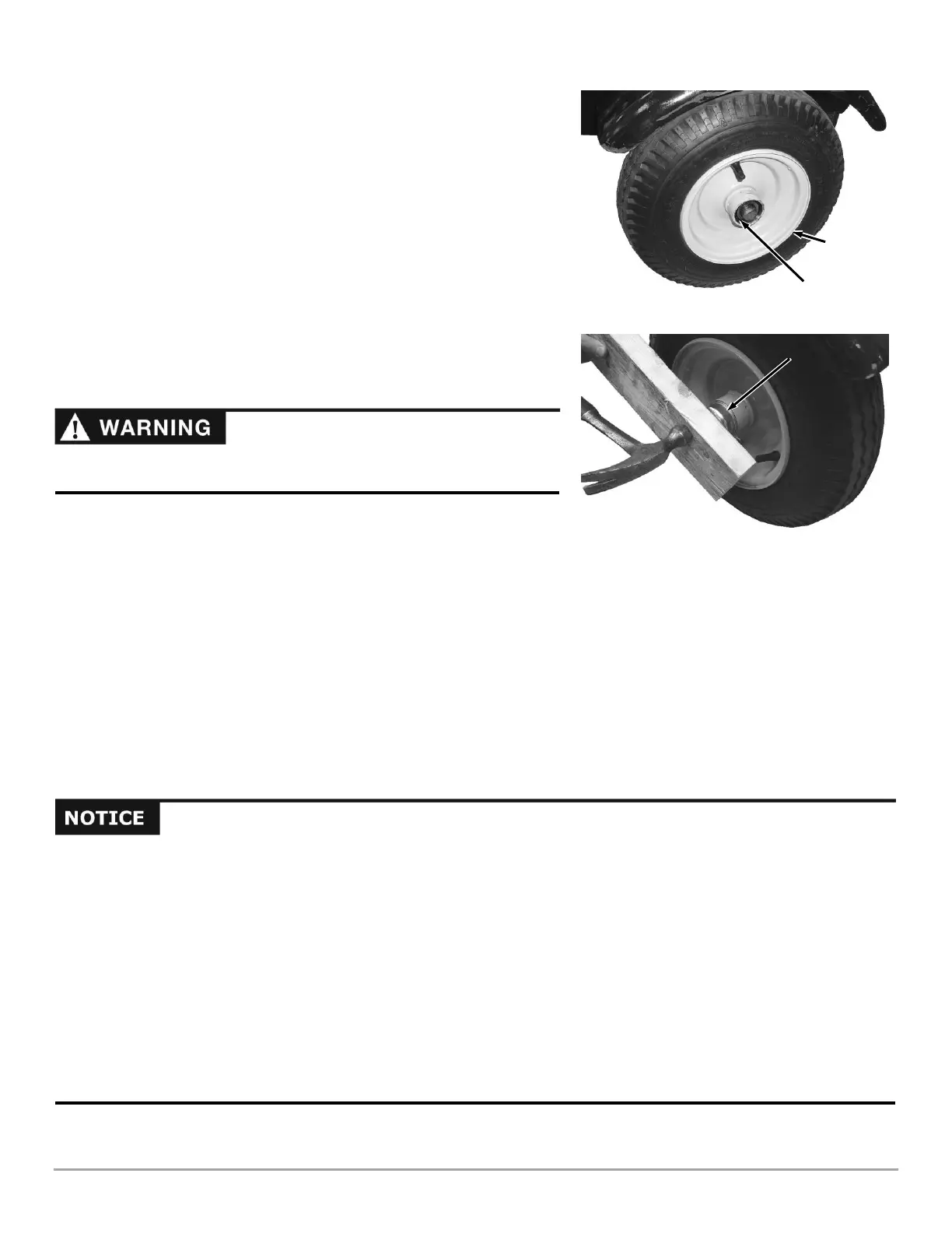
5. Screw the Castle Nut onto the Axle and tighten it with an adjustable
wrench to seat the Bearings (Figure 62).
6. Loosen the Castle Nut and then snug it up to the Bearing lightly.
7. Insert a Cotter Pin through the slots of the Castle Nut and into the hole in
the Axle.
8. Bend the ends of the Cotter Pin with Needle nose Pliers to secure it.
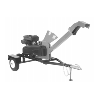
9. Place the Dust Cap onto the Wheel Assembly and secure it by placing a
piece of wood over it and pounding lightly with a hammer until it is against
the lip (Figure 63).
10. Jack the back of the Chipper up and remove the jack Stands.
11. Lower the Chipper to the ground.
12. Check the Tire for proper air pressure and adjust as needed.
Removing and Replacing the Clutch
The design of the Clutch on your machine is for rugged, dependable service; however, it is important to understand the limitations
of a Clutch. The Clutch provides load free starting of the Engine and provides slippage under excessive overloading of the driven
application. These features help protect the Engine from damages such as broken crankshafts and starters. The Shoes and
Springs on the Clutch are normal wear items. If you notice decreased performance of the Clutch, check and replace it if necessary.
The Clutch obtains its power from the Engine RPM. The lower the engagement speed, and the higher the maintained Engine
speed, the more torque the Clutch can transfer to the driven unit. NEVER operate the DR SELF-FEEDING WOOD CHIPPER
Engine at less than full RPM when chipping.
Note: At engine start-up, the engine of your chipper operates under no load until approximately 1800 RPM, at which speed the
centrifugal clutch engages and begins driving the rotor.
 Loading...