28 DR
®
PRO XL520 CHIPPER SHREDDER
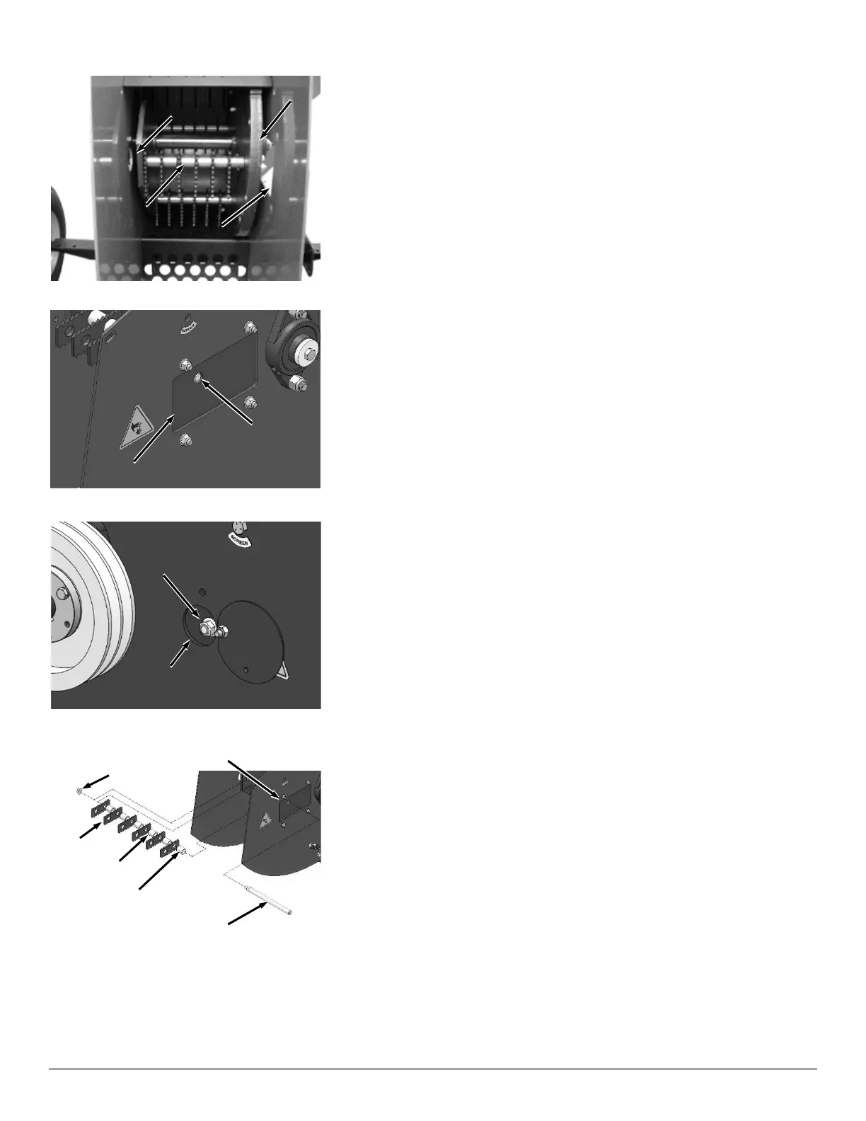
12. Use a Stick to rotate the Rotor until the Hammer Shaft is lined up with the
Access opening and Large Knife Access opening (Figure 45).
13. Use a 3/8" Socket and Socket Wrench, through the Large Knife Access
Opening, to hold the Hammer Shaft Head (Figure 46).
14. Through the Access Opening, use a Socket Wrench with a 9/16″ Deep Socket
to loosen and remove the Flange Locknut (Figure 47). Discard the Locknut.as it
will not be reused
15. Slowly remove the Hammer Shaft through the Knife Access Window, while at
the same time removing the Hammers and Spacers from the Shaft, setting them
aside in the same order and orientation as you remove them (Figure 48).
16. Reverse each Hammer (end to end) to the opposite hole in the Hammer. If
you have already reversed the Hammers (end to end), rotate each Hammer (side
to side) on the same mounting hole.
17. Insert the Hammer Shaft, threaded end first through the Knife Access
Window, into the Rotor as you slide the first Spacer onto the Shaft.
Note: Be sure to reinstall the remaining Hammers and Spacers in the same order that
they were removed. Refer to (Figure 48) for the correct order.
18. As you insert the Shaft further, install a Hammer against the Spacer followed
by the remaining Spacers and Hammers in the same order as they were removed.
19. Through the Access Opening, thread a new Flanged Locknut onto the
Hammer Shaft, (Figure 47).
20. Use a 3/8" socket and socket wrench, through the Large Knife Access
Opening, to hold the Hammer Shaft.
21. Through the Access Opening, use a Torque Wrench with a 9/16″ Deep Socket
and tighten the Flange Nut to 39 Ft-Lbs.
22. Repeat steps 11 through 20 for the remaining three Hammer Shafts.
23. Reposition the Hammer Shaft Access Plate (Figure 44).
24. Reinstall the Knife Access Plate (Figure 43).
25. Reposition the Screen and reinstall the Upper Screen Retaining Bolt and Lock
Nut. Tighten the Upper and Lower Screen Bolts (Figure 42).
26. Reposition the Housing Top Plate and secure with the Housing Top Plate Bolt
and Lock Nut (Figure 41).
27. Tighten the Screen Pivot Bolt, Upper Scroll Bolt and Lower Scroll Bolt.
28. Reinstall the Belt Guard (Figure 40).
29. Re-connect the Negative Battery Terminal Wire and Spark Plug Wires.
 Loading...