12 DR
®
FIELD and BRUSH MOWER
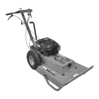
Valve Stem
Protective Cap
Check the Tire Pressure
Tools Needed:
Tire Pressure Gauge
Air Compressor
1. Remove the Valve Stem Protective Cap (Figure 12) and check the tire
pressure with a Tire Pressure Gauge.
2. Compare the tire pressure reading from step 1 with the manufacturer's
recommended tire pressure stamped on the side of the tire.
3. If the pressure is too low, add air through the Valve Stem with an air hose.
4. Replace the Valve Stem Protective Cap when finished.
Deck Pivot Bolt Check/Adjustment
There are two Deck Pivot Carriage Bolts on your DR Field and Brush Mower
Frame. The machine should have been shipped with both Bolts in the highest
position (screwed in fully) as shown (Figure 13). If they are not both in the
highest position, and some of the Carriage Bolt threads are shown, perform the
following procedures.
Tools Needed:
1/2″ Wrench
5/16″ Wrench
Note: The Carriage Bolts should be adjusted all the way up for easy to moderate
mowing. For aggressive mowing adjustment, see “Cutting Brush and Saplings” in
Chapter 3.
1. Loosen both Locknuts using a 1/2" Wrench as you hold the square portion
of the Carriage Bolts using a 5/16" Wrench (Figure 13). Turn the Locknut
down against the Bolt Head.
2. Turn the Carriage Bolts up into the Frame until the Nut is contacting the
Frame.
3. Turn the Locknut against the Frame to lock the Carriage Bolt into position.
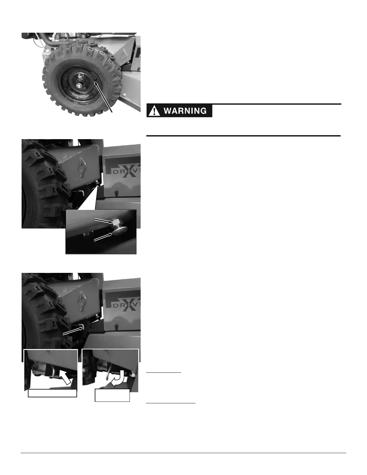
Engaging/Disengaging the Transmissions
The Hydrostatic Transmissions (one for each Wheel) must be engaged for the
Drive Levers to function (machines are shipped in the Drive orientation). They
also can be disengaged when moving the machine by hand. The following
instructions explain this procedure.
Drive Position
1. Push each of the two Neutral Bypass Links in toward the Frame until they
stop (Figure 14).
Free Wheel Position
1. Pull each of the two Neutral Bypass Links out toward the deck and at the
same time toward the outside of the Frame (Figure 14).
Note: The machine will not move easily even with the Transmissions disengaged.
Pulling in reverse may be easier depending on conditions and slope.
Disengaged for
Transporting
Do not over inflate the tires. Inflate to the manufacturers recommended
pressure found on the tires.