EasyManuals Logo

Dräger Interlock 7500 Quick Installation Guide

Dräger Interlock 7500
To Next Page IconTo Next Page
To Previous Page IconTo Previous Page
Page #16 background imageLoading...
Page #16 background image
16 Quick installation guide | Dräger Interlock
®
7500
| Installation
4.4 Example of circuit diagram (here with key switch and starter relay)
49423
Ignition switch
Starter motor
Starter relay
Disconnection
M
V +
V -
Starter relay
(Terminal 50)
Ignition
(Terminal +15, position 2)
Accessories
Off
Plus
Power
brown grey
red
black
blue
Earth
(Terminal 31)
Dräger
Interlock 7500
Control unit
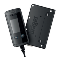
Dräger Interlock 7500
Handset
Starter relay connection
Ignition connection
Positive connection (terminal 30)
Earth

Other manuals for Dräger Interlock 7500

Questions and Answers:

Question and Answer IconNeed help?

Do you have a question about the Dräger Interlock 7500 and is the answer not in the manual?

Dräger Interlock 7500 Specifications

General IconGeneral
BrandDräger
ModelInterlock 7500
CategoryAutomobile Accessories
LanguageEnglish

Related product manuals