3360562 (A3-D-P)
3360562
© Dräger Safety UK Limited
Edition 05 – January 2019 (Edition 01 – June 2012)
Subject to alteration
Draeger Safety UK Limited
Ullswater Close Tel +44 1670 352 891
Blyth, NE24 4RG Fax +44 1670 356 266
United Kingdom www.draeger.com
5.2 Cleaning
CAUTION
Do not exceed 60 °C for drying, and remove components
from the drying facility immediately when dry. Drying time
in a heated dryer must not exceed 30 minutes.
Do not immerse pneumatic or electronic components in
cleaning solutions or water unless following the internal
cleaning procedure in Section 5.2.2.
Thoroughly dry the lung demand valve after cleaning and
disinfecting.
For information about suitable cleaning and disinfecting
agents and their specifications refer to document 9100081
on www.draeger.com/IFU.
Refer also to the instructions for use for the face mask and other
associated equipment.
● Use only clean lint-free cloths
5.2.1 External cleaning
1. Clean the lung demand valve manually using a cloth
moistened with cleaning solution to remove excess dirt.
2. Rinse all components thoroughly with a cloth moistened with
clean water to remove all cleaning and disinfecting agents.
3. Dry all components using a dry cloth, in a heated dryer or in air.
4. Contact service personnel or Dräger if disassembly of the lung
demand valve is required.
5.2.2 Internal cleaning and disinfecting
CAUTION
Internal cleaning and disinfecting may only be carried out
by properly trained personnel. Disassembly of the lung
demand valve by untrained personnel is not permitted and
may damage the equipment.
Ultrasonic cleaning will damage the diaphragm. Dräger
recommend that ultrasonic cleaning methods are not used
for any part of the lung demand valve.
Cleaning solutions will eventually remove lubricants from moving
parts. Carry out functional tests following cleaning, disinfecting
and drying. Re-lubricate moving parts as required.
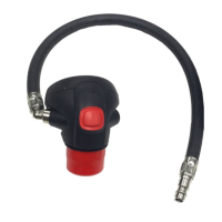
1. Disassemble the lung demand valve as follows:
a. Remove the rubber cover (Fig H, Item 1) from the front of
the lung demand valve housing. Twist the bayonet cap (2)
anticlockwise to remove it (a plate spanner is available
from Dräger for this task – see Section 9). Do not attempt
to remove the spring from the bayonet cap, and do not
stretch, compress or damage the spring during cleaning
and disinfecting (note that the spring is not fitted on
negative-pressure (N-type) lung demand valves).
b. Carefully grip the slip ring (Fig H, Item 3). If required, rotate
the slip ring until the external lugs are free from the
retaining lugs of the housing (Fig I). Remove the slip ring
from the housing.
c. Carefully grip the centre of the diaphragm (Fig H, Item 4)
between the thumb and forefinger. Tilt and remove the
diaphragm from the housing.
d. Replace the rubber cover on the front of the lung demand
valve to protect the balanced piston lever (6).
2. Immerse and manually agitate the lung demand valve,
diaphragm, slip ring and bayonet cap in a cleaning solution.
3. Rinse all parts in clean water.
4. Immerse and manually agitate all parts in a disinfecting
solution.
5. Remove the rubber cover from the front of the lung demand
valve and rinse all parts in clean water, taking care not to
damage the balanced piston lever.
6. Press the reset button (5) to switch off the lung demand valve
and then connect the demand valve hose to a medium-
pressure breathing air supply (minimum of 4 bar).
WARNING
Do not direct the airflow on to the face, eyes or skin.
7. Lightly press the balanced piston lever to blow away any
moisture.
8. Disconnect the air supply and dry all parts using a clean lint-
free cloth or a dedicated drying facility.
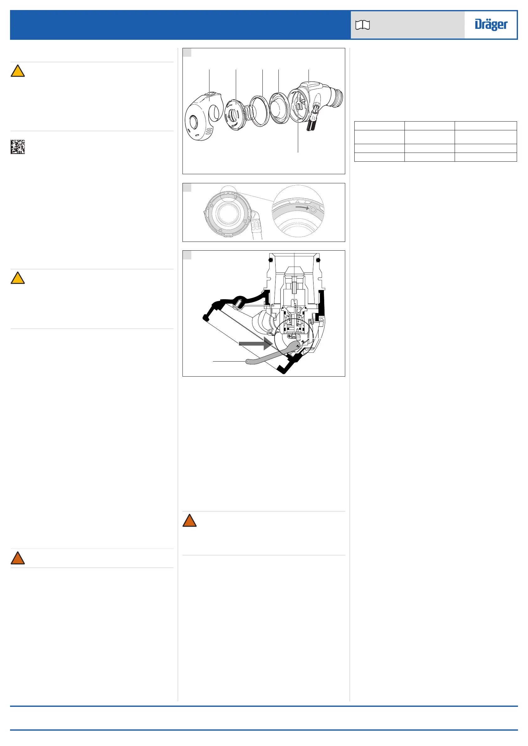
9. If re-lubrication of the moving parts is required, position the
main lever (Fig J, Item 1) and secondary lever (2) as shown.
Apply two short squirts of lubricant (Silkospray silicone
lubricant) to the circled area in the direction indicated by the
arrow.
10. Reassemble the lung demand valve as follows:
a. Carefully install the diaphragm into the lung demand valve
housing.
b. Carefully insert the profiled side of the slip ring into the
housing, ensuring that it sits inside the exterior bead of the
diaphragm.
c. Position the bayonet cap spring in the middle of the
diaphragm. Twist the bayonet cap clockwise to fit it to the
lung demand valve housing.
d. Replace the rubber cover on the front of the lung demand
valve.
11. Press the reset button to switch off the valve.
12. Carry out a full functional test of the lung demand valve (see
Section 5.4).
5.3 Visual inspection
Check that the lung demand valve is clean and undamaged. Pay
particular attention to levers, diaphragm, spring, hoses and
connectors. Typical signs of damage that may affect the operation
of the lung demand valve include impact, abrasion, cutting and
discolouration.
Report damage to trained service personnel or Dräger. Do not use
the lung demand valve until the faults are rectified.
5.4 Functional test
Test the lung demand valve as described in the functional and leak
test procedure in the breathing apparatus Instructions for Use.
WARNING
Failure of the breathing apparatus to meet any of the
standards or parameters described in the functional tests
indicates a system fault. Report the fault to trained service
personnel or contact Dräger. Do not use the breathing
apparatus until the fault condition is rectified.
5.5 Replacing the diaphragm
1. Remove the defective diaphragm and install the replacement.
Instructions for replacing the diaphragm are contained in the
internal cleaning procedure (see Section 5.2.2).
2. Carry out a full functional test of the lung demand valve (see
Section 5.4).
6 Storage
Store the equipment between -15 °C and +25 °C. Ensure that the
environment is dry, free from dust and dirt, and does not subject
the equipment to wear or damage due to abrasion. Do not store
the equipment in direct sunlight.
Route the medium-pressure hose in such a way that the bend
radius is not too small and the hose is not stretched, compressed
or twisted.
7 Disposal
When required, dispose of the lung demand valve in accordance
with national or local regulations for waste disposal.
8 Technical data
Technical data is available from Dräger.
9 Order list
 Loading...