PSS
®
Series Pneumatic Accessories
Second medium-pressure connector - Waist or shoulder mounted
Instructions for Use
3355853 (A3-D-P) Page 2 of 3
See Figure 5 or Figure 6.
5. Remove the screw (1) and then the retention staple (2) from the
manifold (4).
6. PAS
®
Lite and PSS
®
3000/4000 only: Insert the manifold Figure 5, Item 4)
through the 32 mm diameter hole in the left hand frame half.
7. Insert the medium-pressure hose (3) into the manifold port, and press and
hold against the spring.
8. Fully insert the retention staple (2) ensuring correct location into the groove
in the hose end fitting.
9. Check that the hose is securely retained by gently pulling the hose away
from the manifold.
10. Insert and tighten the screw (1) to a torque of 1.2 Nm.
See Figure 7 or Figure 8.
11. Insert the non-return valve (3) into the bore of the manifold and ensure the
O-ring (4) is properly fitted.
12. Insert the manifold connector into the port of the reducer.
13. Fully insert retention staple (2) ensuring correct location into the groove of
the manifold connector.
14. Check that the manifold is securely retained by gently pulling the manifold
away from the reducer body.
15. Insert and tighten the screw (1) to a torque of 1.2 Nm.
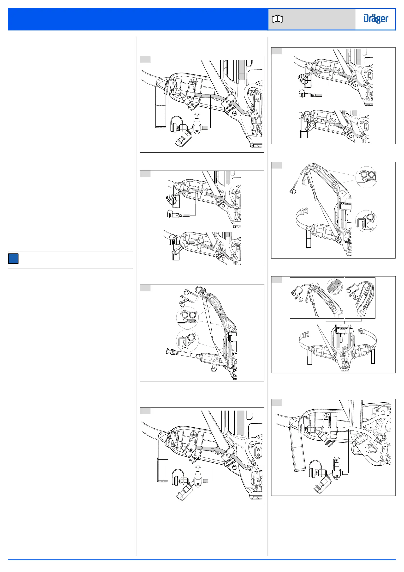
See Figure 9 and Figure 10.
16. For secured connectors, fit the retaining block on to the waist belt as
follows:
a. Loosen the lower screw, remove the upper screw and nut, and open
(rotate) the rear retaining block half (Figure 6).
b. Slide the retaining block on to the waist belt then realign the retaining
block halves (Figure 7).
c. Refit the upper screw (fit the screw into the chamfered cavity and nut
into the hexagonal cavity) and then tighten both screws.
17. See the assembly illustrations (Section 7.1 to Section 7.5) for hose routing,
and hose clip and retaining block positions.
18. For routing hoses inside the backplate of a PSS
®
5000 or PSS
®
AirBoss
breathing apparatus, see the technical manual.
19. When assembly is complete, carry out the functional testing (Section 7.6).
20. PAS
®
Lite and PSS
®
3000/4000 only: fit the pressure reducer into the
backplate:
See Figure 11.
a. Separate the frame halves, and insert the pressure reducer from the
back of the space frame.
b. Align and close the frame halves.
See Figure 2.
c. With the nylon part of the locknut to the outside, insert the locknut into
the left-hand frame half.
NOTICE
Locknuts must grip on the screw. If no interference is felt, replace the
locknut.
d. Insert the screw into the right-hand frame half, and tighten the screw to
3 to 4 Nm.
e. Fit the boot on to the base of the space frame.
See Figure 1.
f. Stretch each leg of the boot fit the tab into the slot in the frame.
g. The existing hoses of the breathing apparatus will have been partially
removed from the channels in the backplate. Refit the hoses as
necessary.
7.1 PSS
®
7000 series
7.1.1 Secured connectors
7.1.2 Unsecured connectors
7.1.3 Shoulder connectors
7.2 PSS
®
5000 series
7.2.1 Secured connectors
7.2.2 Unsecured connectors
7.2.3 Shoulder connectors (external hose routing)
7.2.4 Shoulder connectors (internal hose routing)
7.3 PSS
®
AirBoss
7.3.1 Secured connectors
12
3131
'
13
3125
14
2984
15
3120
16
3119
17
3121
18
3128
19
5415
 Loading...