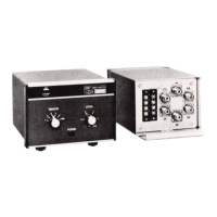
The Drake Model CS-7 Coax Switch is a versatile accessory designed for managing multiple coax-fed antennas and radios in a single installation. It allows for remote switching of up to five antennas to one main coax feed line and local switching of up to five radios (transmitters, receivers, or transceivers) to the same main coax feed line. This design minimizes the amount of coax cabling required for multi-antenna setups and provides grounding for unused inputs, both local and remote. The CS-7 is housed in an attractive enclosure that matches the styling of Drake's 7-line equipment.
Function Description:
The primary function of the CS-7 is to simplify antenna and radio management. It consists of two main components: a remote antenna switch and a local control console. The remote antenna switch, typically mounted outdoors, connects to up to five antennas and a single main transmission line. The control console, located indoors, connects to up to five radios and the main transmission line from the antenna switch.
When the user selects an antenna via the remote switch on the console, the motor-driven switches in the antenna unit rotate to connect the chosen antenna to the main transmission line. Simultaneously, unused antenna inputs are grounded. Similarly, the local switch on the console allows the user to select which of their five radios will be connected to the main transmission line, with unused radio inputs also being grounded. This grounding feature is crucial for safety and reducing interference when equipment is not in use.
The system is designed for ease of use, with a "STANDBY" indicator on the console that illuminates when the motor-driven switches are turning, indicating that the transmission line is temporarily improperly terminated. Users are cautioned to ensure their transmitter is in an "off-the-air" condition during this interval. Once the "STANDBY" light goes out, the selected antenna and radio are properly connected. For station shutdown, the antenna switch can be returned to "GND" (ground) before powering off the unit.
Important Technical Specifications:
- Maximum Input Power: 2000 Watts PEP (Peak Envelope Power), indicating robust power handling capability suitable for high-power amateur radio applications.
- Frequency Range:
- Up to 30 MHz: Insertion of switch changes VSWR (Voltage Standing Wave Ratio) no more than 1.05:1. This excellent VSWR performance ensures minimal signal loss and reflection at lower frequencies, critical for efficient antenna operation.
- From 30 MHz to 150 MHz: Insertion of switch changes VSWR no more than 1.5:1 (for both switches). While slightly higher than at lower frequencies, this still represents good performance for VHF communications.
- Operating Temperature Range: -40°F. to +150°F. (-40°C to 65.5°C), allowing for reliable operation in a wide range of environmental conditions, particularly important for the outdoor antenna switch component.
- Supply Voltage: 120 VAC or 240 VAC Selectable. This flexibility allows the unit to be used in different regions with varying mains voltages, requiring a fuse change if the voltage range is altered.
- Dimensions & Weight (Console):
- Height: 5-1/4" (13.3 cm)
- Width: 6-13/16" (17.3 cm)
- Cabinet Depth: 7-1/16" (17.9 cm)
- Weight: 4.33 lb. (1.96 kg)
- Dimensions & Weight (Remote Antenna Switch):
- Height: 7-1/8" (18.1 cm)
- Width: 5-7/8" (15.0 cm)
- Depth: 4-3/8" (11.1 cm)
- Mounting: 8-3/16" center to center
- Weight: 5 lbs. (2.27 kg)
Usage Features:
- Remote Antenna Switching: The ability to remotely select one of up to five antennas from the control console is a significant convenience, eliminating the need for manual switching at the antenna location.
- Local Radio Switching: The internal local switch allows up to five radios to be connected to the main feed line, streamlining the setup for operators with multiple transceivers, receivers, or transmitters.
- Grounding of Unused Inputs: Both remote antenna inputs and local radio inputs are grounded when not selected. This feature enhances safety by protecting equipment from static discharge and lightning, and reduces potential for interference from unused lines.
- Minimized Coax Cabling: By consolidating multiple antennas and radios through a single main feed line, the CS-7 reduces the overall amount of coax cable needed, simplifying installation and potentially reducing signal loss.
- "RAIN-HAT" Construction: The remote antenna switch is designed with "RAIN-HAT" construction, enabling it to operate reliably in adverse weather conditions, which is essential for outdoor equipment.
- Universal Mounting Bracket: The antenna switch features a universal mounting bracket, allowing it to be easily mounted to the side of a tower, mast, or a flat surface.
- Voltage Selectability: The console offers selectable 120 VAC or 240 VAC operation, making it adaptable to different power grids worldwide.
Maintenance Features:
- Warranty: R. L. Drake Company provides a limited warranty of ninety (90) days from the date of original purchase, covering defects in material or workmanship (excluding tubes and RF output transistors). Warranty service requires completing a registration card, notifying Drake of the defect with detailed information, and delivering or shipping the product to Drake or an authorized service facility.
- Installation Recommendations: The manual emphasizes careful unpacking and inspection for shipping damage, advising users to retain the original carton and packing material for potential claims or future storage/returns.
- Cable Management: For the remote antenna switch, it is recommended to use an 8-conductor cable for control signals and to utilize the cable clamp to relieve strain on terminal strip connections.
- Environmental Protection: After connecting the 8-conductor cable to the antenna switch, it is recommended to coat the terminal strips with a silicone sealer or RTV to protect them from environmental elements.
- Grounding: Proper grounding of the antenna switch is stressed. It is advisable to connect a strap from the ground lug on the antenna switch to a good earth ground or to the tower itself (if it provides a good earth ground) to ensure effective grounding of antennas. This is absolutely necessary if the antenna switch is mounted to a structure that is not a good earth ground.
- Fuse Replacement: When changing the supply voltage from 120 VAC to 240 VAC, it is necessary to change the fuse rating to a 3/4 amp slow blow fuse, as detailed in the wiring diagrams.