Page 2 of 2
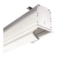
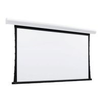
Salara by Draper
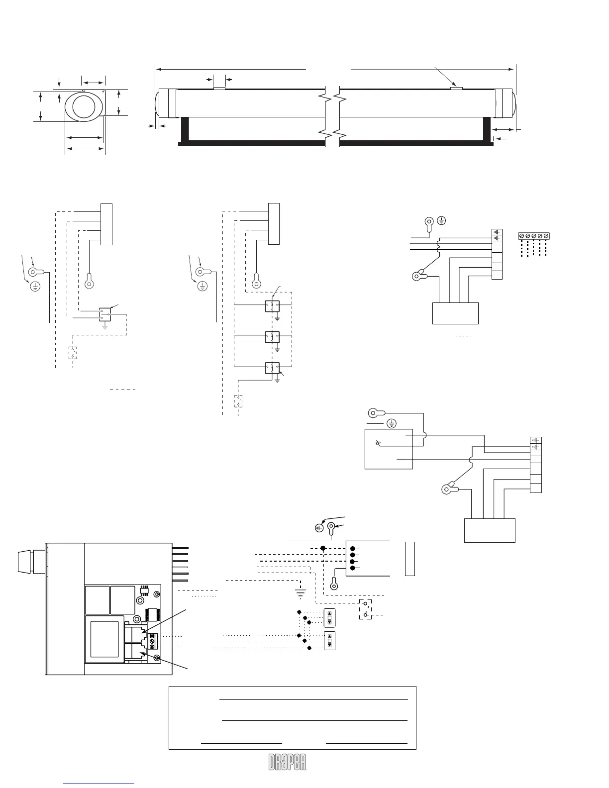
Wiring Diagrams
Salara—Dimensions
3
13
/16"
5
/16"
3
/8"
1
3
/8"
Case Length
Viewing Surface
5
1
/16"
5
7
/16"
3
1
/8"
3
7
/16"
5
/16"
3
13
/16"
Floating Mounting Brackets
Hardwired with Built-in IR
Plug & Play
TM
IR
Single Station Control
Control
switch
Single gang box by others
Min. 4" x 2
1
/8" x 1
7
/8" deep
Red
Black
Blue
Location of key
operated on-off
switch if furnished
To 110-120V Line
Green/Yellow
White
Red
Black
Green
Motor
Chassis ground label
Screw attaching
endcap to case
Multiple Station Control
Dashed wiring
by electrician
Blue
Blue
Black
Red
Red
Cap off with wire
nut and tape
Black
Blue
Red
Black
Single gang box by others
Min. 4" x 2
1
/8" x 1
7
/8" deep.
3 shown. More or less equally
feasible.
Location of key
operated on-off
switch if furnished
To 110-120V Line
Green
White
Red
Black
Green/Yellow
Motor
Chassis ground label
Screw attaching
endcap to case
Dashed wiring by others
Salara
www.draperinc.com
(765) 987-799
Standard 110-120V AC IEC
(no external wiring necessary)
See separate Serial Communication-RS232 Instruction
sheet for enabling RS232 with the MC1.
3 Button Wall Switch
DOWN - Black
COM - White
UP - Red
White-Common to screen & 110-120V AC Neutral
Red-to screen (directional)
Brown-to screen (directional)
Yellow-to 110-120V AC-Hot
Black-to 110-120V AC-Hot
Green(Ground)
Eye Port for IR Eye, RF Receiver or LED
Wall Switch. For more than one of
these, a splitter is required.
Aux Port for connecting additional LVC-III
modules (up to six total can be linked-
connect from Aux to Eye).
Dashed wiring by electrician
Low voltage wiring by others
White (Common)
Red (Up)
Black (Down)
Green
(Motor Ground)
Location of key
operated on-off
switch if furnished
To
110-120V
Line
Internal Screen Wiring
STOP
Control
Switches
24v DC
STOP
Green/Yellow
Motor
Chassis ground label
Screw attaching
endcap to case
PROJECT:
SUPPLIER:
DATE: REVISED:
Dashed Wiring
By Others
L N Neu Dir Dir
Green/Yellow
Black
White
Green
Green
White
Red
Black
Motor
Chassis ground label
next to screw
(1) #10 Ring
Terminal on
each ground wire
MotorAC In
RS232 Data from Control System
RS232 Data to Control System
Signal Ground & Manual Switch Commo
Manual Down Switch
Manual Up Switch
Low Voltage & Remote Control
L N Neu Dir Dir
Green
Green
White
Red
Black
Motor
Chassis
ground
label
Motor/PCB Ground
(1) #10 Ring
Terminal on
each ground wire
MotorAC In
Line 1
N
IEC Inlet
Green/Yellow
Black
White