Do you have a question about the Draper Targa and is the answer not in the manual?
Read and understand all safety warnings and initial steps before commencing installation.
Instructions for securing the screen directly to a wall using appropriate hardware.
Guidance on suspending the screen using S-hooks and chains from structural supports.
Details on using extension and floating brackets for wall or ceiling installations.
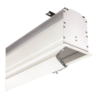
Procedures for recessing the screen, including trim kit considerations for drop ceilings.
How to adjust the down and up travel limits for standard and quiet motors.
Steps to set screen limits for ILT motors using the wall switch programming.
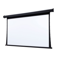
The Targa is an electrically operated projection screen featuring a motor-in-roller design, intended for both residential and commercial applications. It is designed for easy installation and operation, with various control options and safety features to ensure reliable performance.
The Targa projection screen provides a retractable viewing surface for projectors, allowing users to deploy or retract the screen with the push of a button or through integrated control systems. The motor-in-roller design ensures smooth and quiet operation, while the robust construction is built for durability. The screen operates on a standard 110-120V, 60 Hz electrical supply, with a low current draw of 1.1 Amps and a duty cycle of 28 seconds on, 4 minutes off.
The Targa offers a variety of usage features and control options to suit different installation needs:
Control Options:
Limit Adjustments: The screen's upper and lower limits are factory set but can be fine-tuned for specific installation requirements.
Internal Low-Voltage Control Unit (LVC-IV): This optional unit is integrated into the screen housing and provides advanced control capabilities. It can be accessed by removing two star head screws from the motor end of the screen housing and then removing the access panel. The LVC-IV allows for single or multiple projection screen wiring and supports various inputs like 3-button wall switches, RS232/485, IR eye input, and low-voltage triggers. Up to six LVC-IV modules can be linked together for multi-screen installations.
The Targa is designed for ease of maintenance and troubleshooting:
The manual emphasizes several critical safety guidelines for installation and operation:
| Diagonal | 106 \ |
|---|---|
| Drive type | Motorized |
| Tensioned screen | No |
| Diagonal (metric) | 269.24 cm |
| Native aspect ratio | 16:9 |
| Viewable screen width (W) | 2336.8 mm |
| Viewable screen height (H) | 1320.8 mm |
| Overall screen size (Height x Width) | 162.56 x 243.84 cm |
| Mounting type | Ceiling |
| Product color | White |
| Easy to install | Yes |
| Quantity per pack | 1 pc(s) |
| Input voltage | 220 V |