Internal LVC-IV - Single or Multiple Projection Screen Wiring Diagram
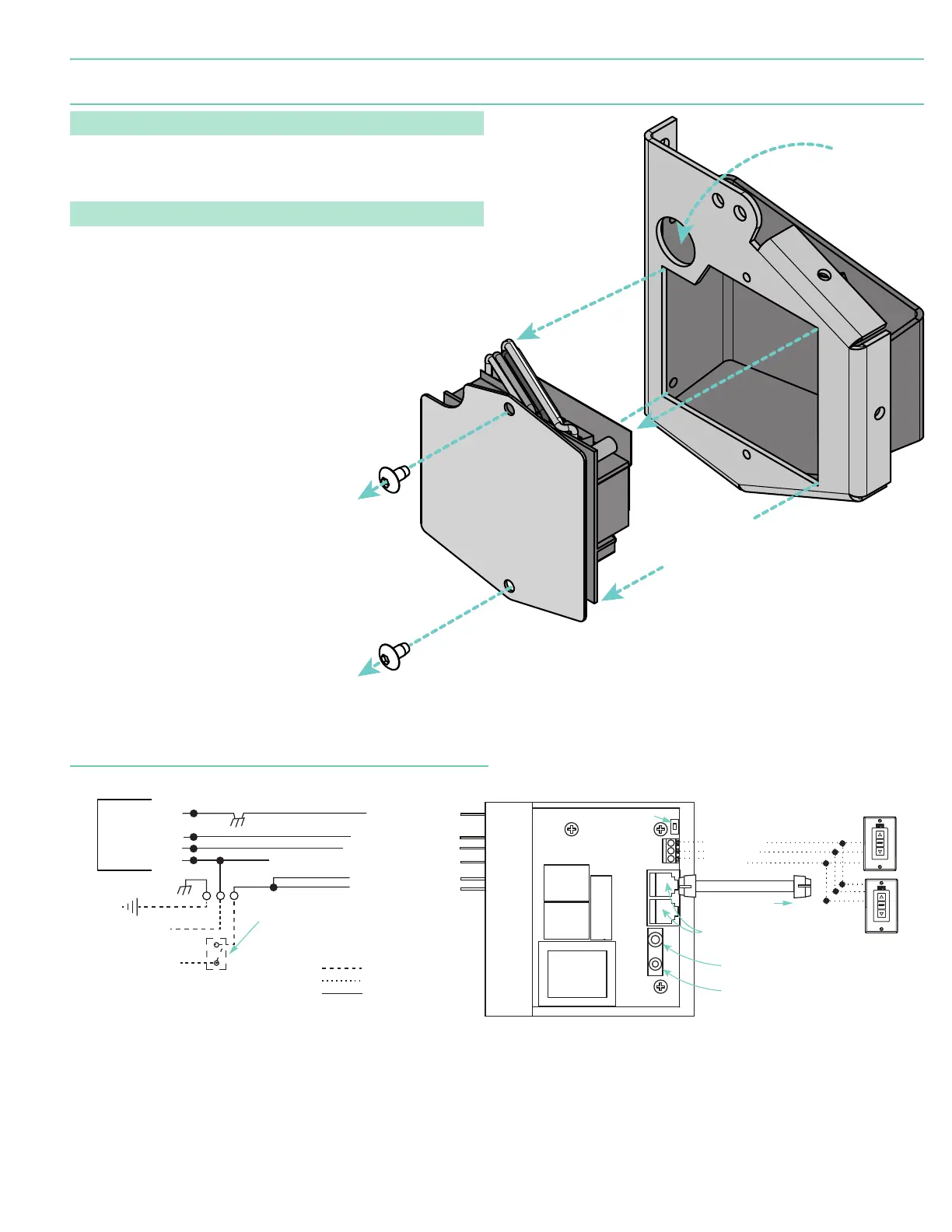
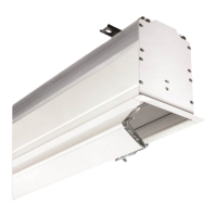
Section 5 - Accessing Internal Low-Voltage Control Unit
(LVC-IV)
PLEASE NOTE: Applies ONLY if Unit is built into case.
1. Locate LVC-IV Unit.
2. Remove the two
(2)
star head screws from the motor end of the screen housing.
3. Remove the access panel with the LVC-IV from the screen housing.
PLEASE NOTE: Internal LVC-IV will increase overall case length by 1 ⁄"
(46 mm)
.
Remove two (2)
screws from
endcap.
Remove
access panel
with LVC-IV.
*A second electrical connection hole
is included in the screen housing
in order to separate Low-Voltage
and High-Voltage Wiring.
Connection
Hole*
Internal LVC-IV - Single or Multiple
Projection Screen Wiring Diagram
Black-to 110V-120V AC-Hot
Red-to screen (directional)
Brown-to screen (directional)
Yellow-to 110V-120V AC-Hot
White -Common to screen & 110V-120V AC Neutral
N
TO: MOTOR LEADS
3-Button Wall Switch
DOWN - Black
COM - White
UP - Red
Electrically Straight
Data Cable to more
LVC-IV modules.*
*A maximum of six (6)
LVC-IV modules can be
linked together.
FUSE - 3.15 AMP
250 VAC 5x20mm
Dashed wiring by electrician
Factory wiring
Low-voltage wiring by others
To
110-120 VAC
Line
Green/Yellow (Ground)
White (Common)
Red (Up)
Black (Down)
INTERNAL SCREEN WIRING
Green/Yellow
(Motor Gr
ound)
Location of key
operated on-off
switch if furnished.
IR Eye Input
Low-Voltage
Trigger
4-28 VDC
RS232/485
Inputs/Outputs
Wall Switch
L1
GND
Receiver
Button
WIRING DIAGRAM -
Internal LVC-IV (Low-Voltage Control Module)
page 5 of 8
Targa