Overview - Components
CAUTION
Read and understand all warnings
(Page 2 of this document)
before beginning installation.
Contents
Overview - Components ............................................................................................... 1
Section 1 - Removing Shipping Brackets
(Figure 1)
..................................................1
Section 2 - Electrical Connections .............................................................................2
Section 3 - Operation....................................................................................................2
PLEASE READ - Safety Information ............................................................................ 2
Section 4 - Hanging Screen and Methods of Installation ....................................... 3
Section 5 - Limit Adjustments ..................................................................................... 4
Section 6 - Tab-Tension Adjustment Procedure ......................................................4
Section 7 - Accessing Internal Low-Voltage Control Unit
(LVC-IV)
.........................5
Section 8 - Dimensions ................................................................................................5
Section 9 - Wiring Diagrams: Standard and Quiet Motor .......................................6
Section 10 - Wiring Diagrams: Motor with internal low-voltage controller .........7
Section 1 - Removing Shipping Brackets
(Figure 1)
CAUTION: Shipping support brackets must be removed from bracket
clamps at each end of dowel before initial operation, and before
screen is operated in UP direction.
CAUTION: Raise and lower viewing surface several times to confirm
satisfactory operation. If viewing surface does not operate properly,
turn power off and check electrical connections.
Cable
Exit
Junction Box
(without cover)
Tension
Cable
Dowel
VIEWING SURFACE
VIEWING SURFACE
CASE
CASE
4. Retighten dowel
endcap screws.
4. Retighten dowel
endcap screws.
3. Loosen screws
and remove
shipping bracket.
2. Run the screen
DOWN to expose
dowel screws.
2. Run the screen
DOWN to expose
dowel screws.
1. Remove fasteners
from bracket clamps.
1. Remove fasteners
from bracket clamps.
Figure 1
TOOLS
REQUIRED
TAPE MEASURE
HARDWARE
(by others)
LEVEL
Draper, Inc. | 411 S. Pearl St. Spiceland, IN 47385
draperinc.com | 765.987.7999 | 800.238.7999
© 2020 All Rights Reserved | FORM: Premier_Inst20
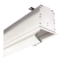
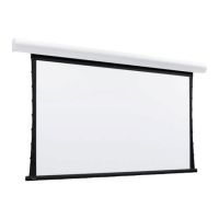
Premier
Electrically operated projection screen with motor-in-roller
INSTRUCTIONS
INSTALLATION & OPERATION
If you have any difficulties installing or servicing your
Premier projection screen, call your dealer or Draper, Inc.