Please Note: Do not wire motors in parallel.
Section 9 - Wiring Diagrams: Standard and Quiet Motor
Single Station Control
White (Common)
Black (Down)
Red (Up)
Green (Ground)
Control
switch
Blue
Black
Red
Location of key
operated on-off
switch if furnished.
To 110-120V Line
Single gang box by others.
Min. 4" x 21⁄8" x 17⁄8" deep.
(102mm x 54mm x 48mm)
Dashed wiring
by electrician.
110-120V MOTOR AND QUIET MOTOR
Internal Screen Wiring
GND
L1
N
Red-to screen
(directional)
Brown-to screen
(directional)
Yellow-to 110V-120V AC-Hot
Black-to 110V-120V AC-Hot
White-Common to screen
& 110V-120V AC Neutral
Green/Yellow
(Ground)
Dashed wiring by electrician
Factory wiring
Low-voltage wiring by others
IR Eye Input
LVC-IV motor lead bundle
LVC-IV AC power input bundle
Low-Voltage
Trigger
4-28 VDC
RS232/485
Inputs/Outputs
3 Button Wall Switch
DOWN - Black
COM - White
UP - Red
Wall Switch
Electrically Straight
Data Cable to more
LVC-IV modules.*
Location of key
operated on-off
switch if furnished.
To
110-120 VAC
Line
*A maximum of six (6)
LVC-IV modules can
be linked together.
Receiver
Button
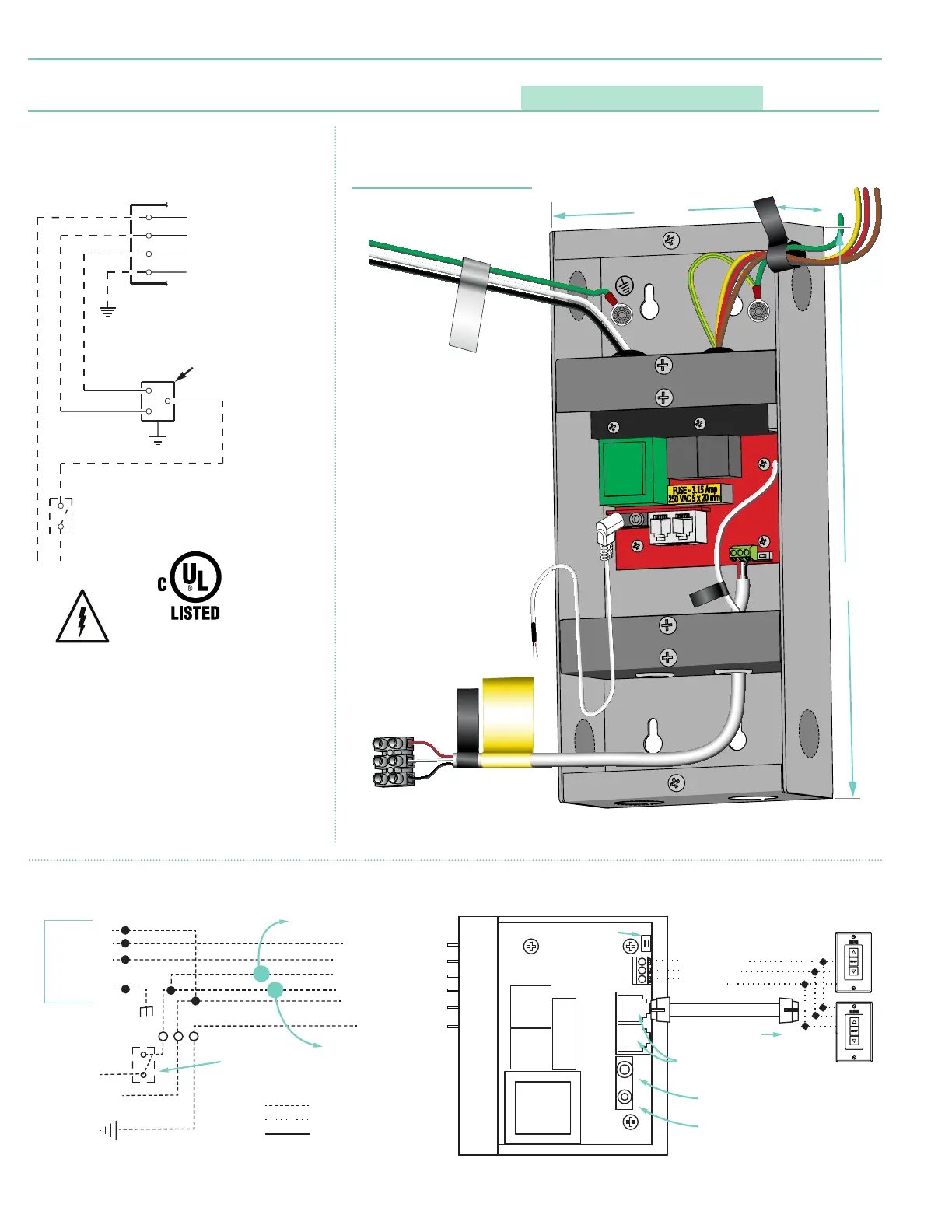
FUSE - 3.15 AMP
250 VAC 5x20mm
External LVC-IV - Single or Multiple Projection Screen Wiring Diagram
White
(Common)
Red
(Up)
Black
(Down)
INTERNAL SCREEN WIRING
Green/Yellow
(Motor Ground)
TO: MOTOR LEADS
External LVC-IV Junction Box
2.214"
(56mm)
4.5"
(114mm)
10.39"
(264mm)
MOTOR LEADS
WALL SWITCH
AC POWER INPUT
WARNING
DRY CONTACT
CLOSURE ONLY.
APPLYING VOLTAGE
HERE WILL DAMAGE
CONTROLLER.
RF Antenna
Wire
page 6 of 7
Premier