Section 4 - Limit Adjustments
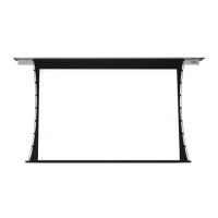
Section 4.2 - ILT Motors with Internal Low-Voltage Control Limit Adjustments
(Fig. 8)
1. Connect ILT switch to motor via terminal blocks, or via modular
port using a four conductor modular cable. When using modular
cable, cable connectors MUST NOT be crimped in reverse, as
with standard telephone cable.
(For Dry Contacts Wiring Diagram, see p.7.)
2. Set slide switch to lower position. Hold DOWN button to
move viewing surface to desired lower limit. If screen moves
in opposite direction, release DOWN button and hold STOP
button for 4 seconds. This reverses operation of UP and DOWN
switches.
3. Move slide switch into center position. Wait several seconds.
Please Note: Do Not move slide switch from DOWN to UP
in one motion. This will set limits in same position.
4. Set slide switch to higher position. Move viewing surface to
desired upper limit by holding UP button on wall switch.
5. Return slide switch to center position to resume normal
operation.
6. To set viewing surface to alternate format position, move viewing
surface to desired position and press STOP button. Hold STOP
button for at least 3 seconds to record position.
Please Note: This screen is not tested for alternate positions;
surface flatness cannot be guaranteed.
POSITION FUNCTION
DOWN Set LOWER limit
UP Set UPPER limit
CENTER Normal Operation
Please Note: 5V DC must be connected to be
able to set limits using the wall switch.
BACK VIEW OF WALL SWITCH
U
p
D
o
w
n
C
o
m
m
o
n
+
5V
DC
To Motor
with
Built-In (ILT)
Low Voltage
Slide
Switch
To Motor
with
Built-In (ILT)
Low Voltage
Please Note: Hold STOP button for 3-5 seconds while in programming mode to reverse motor direction.
Figure 7
Figure 6
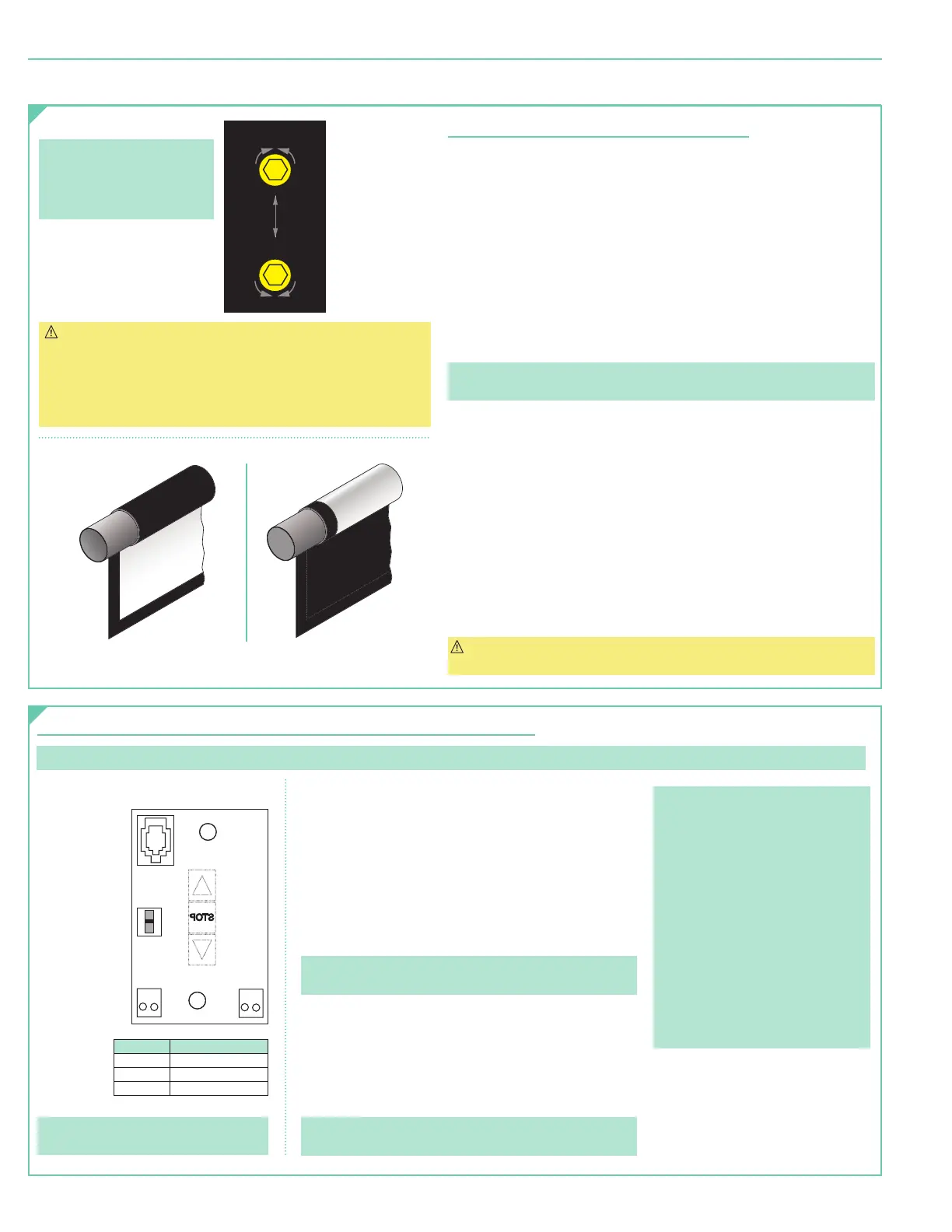
Section 4.1 - Standard Motors/Quiet Motors
(Fig. 6)
Section 4.1.1 - "Down" Limit Adjustment
(requires
5/32
" (4 mm) hex key)
To Reduce Screen Drop:
1. Raise screen surface approximately 1'
(30 cm)
above desired setting
and turn switch off.
2. Turn DOWN
(I)
limit screw clockwise
(3 screw turns =
½
roller revolution)
.
3. Test by lowering screen. Repeat steps 1 and 2 until desired position is reached.
To Increase Screen Drop:
1. Lower screen to down limit.
2. With down switch off, turn DOWN
(I)
limit screw counterclockwise
(3 screw turns = ½ roller revolution)
to increase drop.
3. Test by raising screen approximately 1'
(30 cm)
then down to new
down limit.
4. Repeat steps 2 and 3 until desired position reached.
Please Note: For Quiet Motor with alternate limit screws:
WHITE screw = UP and RED screw = DOWN.
Section 4.1.2 - "Up" Limit Adjustment
If Screen Raises Too High:
1. Lower screen surface approx. 1'
(30 cm)
below desired setting
and turn switch off.
2. Turn UP
(II)
limit screw clockwise
(3 screw turns = ½ roller revolution).
3. Test by advancing screen up.
4. Repeat steps 1 through 3 until desired position is reached.
If Screen Needs to Raise Higher:
1. Lower screen surface approx. 1'
(30 cm)
below desired setting
and turn switch off.
2. With UP switch off, turn UP
(II)
limit screw counterclockwise
(3 screw turns =
½
roller revolution)
.
3. Repeat steps 1 and 2 until desired position is reached.
CAUTION: DO NOT allow dowel to wrap over roller when operating screen!
This could damage screen.
Please Note: Screen limits are
factory set. Instructions below
for minor adjustments only.
Please check with Draper prior
to resetting screen limits.
CAUTION:
- Be sure all switches are in “off”
position before adjusting limit
switches.
- Be prepared to shut off manually
while testing.
- Screen may be damaged by
lowering it too far and
exposing roller.
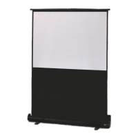
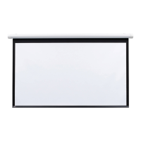
Figure 8
Left hand motor:
White Socket—Down
Yellow Socket—Up
Right hand motor:
White Socket—Up
Yellow Socket—Down
Left hand motor:
White Socket—Up
Yellow Socket—Down
Right hand motor:
White Socket—Down
Yellow Socket—Up
White Socket—Down
Yellow Socket—Up
White Socket—Up
Yellow Socket—Down
W
Motor
End
Audience
Side
Motor
End
Audience
Side
Reverse Roll
Motor
End
Back
Side
I
I
+
+
DOWN Limit (I)
Clockwise decreases
down travel.
UP Limit (II)
Counterclockwise
increases up travel.
DOWN Limit
(I)
:
Clockwise
decreases
down travel.
UP Limit
(II)
:
Counterclockwise
increases up travel.
STANDARD
ROLL
REVERSE
ROLL
Please Note: Press and release UP button
on switch to move screen to upper limit.
Press and release DOWN button to move
screen to lower limit.
• While motor is in motion, press STOP
button for less than 2 seconds to stop
viewing surface at present position.
• Once motor is stopped, press STOP
button to move viewing surface to
alternate format position.
• Hold STOP button, when motor is at
rest or in motion, for 3-5 seconds to
record new alternate format position.
• Hold STOP button for 3-5 seconds
while in programming mode to reverse
motor direction.
page 4 of 8
Targa