EasyManua.ls Logo

Draper SLX - User Manual

Draper SLX
8 pages
Print Icon
To Next Page IconTo Next Page
Loading...
CAUTION
Read and understand
all warnings
(Page 2
of this document)
before
beginning installation.
TOOLS REQUIRED
Contents
Overview - Components .......................................................................................1
Overview - Planning ..............................................................................................1
PLEASE READ - Safety Information ....................................................................2
Section 1 - Hanging Unit ......................................................................................3
Section 2 - Operation............................................................................................3
Section 3 - Adjusting for Level or Center of Gravity ........................................ 4
Section 4 - Installing Projector ...........................................................................4
Section 5 - Attaching Universal Projector Mount to Projector Pan ..............4
Section 6 - Installing Optional Environmental Air Space Housing ...............5
Installing Optional Ceiling Trim Kit .............................................................................5
Section 7 - Installing Ceiling Closure .................................................................5
Section 8 - Connecting Controls to Data Cable Splitter Board .................... 6
Section 9 - Clearing and Resetting Show Position ..........................................6
Section 10 - Optional Delay Feature ...................................................................6
Section 11 - Electrical Connections ...................................................................7
Section 12 - Operation ..........................................................................................7
Section 13 - Testing Safety Limit Switches ....................................................... 7
Section 14 - Adjusting Limit Switches ...............................................................7
Section 15 - Wiring Schematic ............................................................................8
Section 16 - Dimensions ......................................................................................8
Overview - Components
Overview - Planning
1.
Based on screen location and projector
specifications, determine proper position for
projector installation.
2.
Confirm that there is adequate space for
installation and operation. Minimum clearance
above ceiling level varies according to height
of projector, optional projector mounting
bracket, optional ceiling closure and optional
Environmental Housing.
3.
Arrange to provide service access to the unit.
4.
Installer is to provide an RJ45 cable, for
each switch, with a connector on one end to
connect to the lift and open on the other end
to connect to each switch
5.
When installed with Environmental Air Space Housing
unit is suitable for use in an environmental air space
in accordance with Section 300.22
(C)
of the National
Electrical Code, and Section 2-128, 12-010
(3)
and 12-100 of
the Canadian Electrical Code, Part 1, CSA C22.1.
6.
Total capacity of lift including cables, closure, projector,
and bracket:
As Soon As Lift Arrives
1.
Open carton and inspect for damage.
2.
Locate the following parts:
A.
The unit itself
B.
Controls
C.
Any optional equipment
SLX10
453 LBS 205KG
SLX14
435 LBS 197KG
SLX17
418 LBS 190KG
SLX21
393 LBS 178KG
SLX24
375 LBS 170KG
SLX28
350 LBS 159KG
PIN OUTS
1 - UP
2 - DOWN
3 - NOT USED
4 - NOT USED
5 - NOT USED
6 - NOT USED
7 - COM
8 - COM
MAKING YOUR OWN CABLES?
POWER DRILL
PENCIL
TAPE MEASURE
HARDWARE
(by others)
LEVEL
PLIERS
HEX WRENCH
SCREWDRIVER
Draper, Inc. | 411 S. Pearl St. Spiceland, IN 47385
draperinc.com | 765.987.7999 | 800.238.7999
© 2022 All Rights Reserved | FORM: ScissorLiftSLX_115VAC_Inst22
Scissor Lift - SLX 115V
Ceiling-recessed video projector lift
INSTRUCTIONS
INSTALLATION & OPERATION
If you have any difficulties installing or servicing your
Scissor Lift SLX, call your dealer or Draper, Inc.
NOTICE:
These Instructions apply ONLY
to Scissor Lifts Manufactured
AFTER October, 15th, 2022
Instructions for Lifts Manufactured Prior
to this date can be found: HERE

Other manuals for Draper SLX

Question and Answer IconNeed help?

Do you have a question about the Draper SLX and is the answer not in the manual?

Summary

Overview - Components

Overview - Planning

Safety Information and Warnings

General Safety Precautions

Covers essential safety guidelines from DANGER to WARNINGs for unit operation and handling.

Installation and Operation Warnings

Highlights critical warnings and cautions related to installation, calibration, and safe operation procedures.

Section 1 - Hanging Unit

Installation Guidelines

Provides essential guidelines for securely mounting the lift unit, including fastener requirements and structural integrity.

Section 2 - Operation

Control Systems and Options

Details available control systems like LVC-S, SP-KSM, IR, RF, and Low Voltage Trigger inputs.

Operating Procedures

Explains initial operation, setting show positions, and using service controls for calibration.

Section 3 - Adjusting for Level or Center of Gravity

Preferred Method - Adjusting Projector Pan

Step-by-step guide to adjust the projector pan for level and center of gravity using screws.

Secondary Method - Adjusting Lifting Cable Bar

Alternative method to adjust the lifting cable bar for pan alignment if the preferred method fails.

Section 4 - Installing Projector

Projector Installation Details

Covers projector mount options, size limitations based on closures, and mounting screw considerations.

Section 5 - Attaching Universal Projector Mount to Projector Pan

Section 6 - Installing Optional Environmental Air Space Housing

Section 7 - Installing Ceiling Closure

Ceiling Tile Installation

Instructions for integrating ceiling tiles with the closure panel for a seamless finish.

Large Closure Attachment

Procedure for attaching brackets and rods for large ceiling closure panels.

Rod Adjustment and Closure Fit

Guides adjustment of threaded rods to ensure proper closure positioning and fit relative to ceiling.

Section 8 - Connecting Controls to Data Cable Splitter Board

Control Connections Overview

Details connections for various controls to the main splitter board using RJ45 connectors.

Data Cable Splitter Board Diagram

Illustrates the layout and connections on the data cable splitter board.

Section 9 - Changing the Show Position

Entering Programming Mode

Steps to enter the lift's programming mode using wall and key switches.

Procedure for Setting Show Position

Guide to setting the desired 'show' position using wall and key switch inputs.

Exiting Programming Mode

Instructions on how to exit programming mode and confirm the new show position.

Section 10 - Optional Delay Feature

Section 11 Electrical Connections

Power and Wiring Requirements

Details electrical specifications including voltage, current draw, and wiring precautions.

Section 12 - Wiring Schematic

Section 13 RS232 and RS485 Serial Port Protocols

Sending Lift Commands

Lists serial commands for controlling lift functions like extend, retract, and position.

COM Port Settings

Specifies required COM port settings for serial communication with the lift.

Section 14 - Adjusting Limit Switches

Adjusting Fully Down Position

Details on adjusting the factory preset down limit switch for the fully down position.

Section 17 - Dimensions

Overview

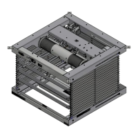
The Scissor Lift - SLX 115V is a ceiling-recessed video projector lift designed for discreet and secure projector installation. It is suitable for use in various environments, including those requiring compliance with environmental air space regulations.

Function Description:

The Scissor Lift - SLX 115V is designed to store a video projector above the ceiling and lower it to a "show position" for use, then retract it back into the ceiling when not in use. This mechanism ensures the projector is out of sight and protected when not in operation. The lift is controlled via various methods, including a low voltage control switch, key-operated switch, optional infrared (IR) control, and optional radio frequency (RF) control. It also supports serial communication (RS232/RS485) for integration into network control systems. The unit features adjustable limit switches to define the fully up (closed) and fully down (show/maintenance) positions, ensuring precise and repeatable operation. An optional environmental air space housing allows for installation in specific air spaces, while an optional ceiling closure provides a finished look that integrates with the surrounding ceiling.

Important Technical Specifications:

  • Power: 115V AC, 60 Hz.
  • Current Draw: 14 amps total (2 amps for lift, 12 amps for outlet).
  • Weight Capacity (including cables, closure, projector, and bracket):
    • SLX10: 453 LBS (205KG)
    • SLX14: 435 LBS (197KG)
    • SLX17: 418 LBS (190KG)
    • SLX21: 393 LBS (178KG)
    • SLX24: 375 LBS (170KG)
    • SLX28: 350 LBS (159KG)
  • Minimum Projector Weight for Operation: 15 lbs. (to prevent cables from unspooling).
  • Projector Pan Adjustments: Can be moved forward or back for level and center of gravity adjustments.
  • Maximum Projector Size (with small closure): 18" x 8¾" (45.7 x 22.2 cm) (width x length x Environmental Air Space Housing height).
  • Maximum Projector Size (with large closure): 18" x 18" (45.7 x 45.7 cm) (width x length x housing height).
  • Closed Height (from 14 1/16" (35.6cm) for SLX10 to 25 5/16" (63.4cm) for SLX28).
  • Extended Height (from 10'7" (322.6cm) for SLX10 to 28'5" (866.1cm) for SLX28).
  • Control Ports: RJ45 connectors for wall switch, key switch, serial (RS-232, RS-485), IR eye, and low voltage trigger.
  • Serial Communication Settings: 9600 baud, 8 data bits, no parity, 1 stop bit, X On/X Off flow control.
  • Safety Certifications: cULus Listed.

Usage Features:

  • Multiple Control Options: Includes a 3-button Low Voltage Control (LVC-S) switch for UP-STOP-DOWN operation and a Key Operated Switch (SP-KSM) for service position control. Optional IR and RF transmitters are available for wireless control.
  • Programmable Show Position: The lift's "show position" can be easily programmed using a combination of the wall switch and key switch. This allows installers to set the exact desired projection height.
  • Adjustable Projector Pan: The projector pan can be adjusted forward or backward to achieve optimal projector alignment and balance, ensuring the projector is level and centered.
  • Environmental Air Space Housing (Optional): When installed with this housing, the unit is suitable for use in environmental air spaces, complying with relevant electrical codes (Section 300.22(C) of the National Electrical Code, and Canadian Electrical Code Part 1, CSA C22.1).
  • Ceiling Closure System (Optional): Integrates with the ceiling for a clean, concealed installation. The closure can be adjusted to stop just short of the ceiling in the closed position to prevent motor cycling and potential damage.
  • Delay Feature (Optional): An optional delay switch can be installed, which must be in the "Delay On" position for normal operation. It should be switched to "Off" when adjusting the show position.
  • Dry Contact Closure Support: Additional momentary switches or control systems using dry contact closure can be connected for multiple station control.
  • Universal Projector Mount (Optional): Draper's optional universal projector mount can be used to secure projectors weighing up to 26 lbs (12kg).

Maintenance Features:

  • Service Position: The key-operated switch allows the lift to be moved to a "service position," facilitating maintenance and adjustments.
  • Adjustable Limit Switches: The DOWN limit switch, which controls the fully down (maintenance) position, can be manually adjusted by loosening a screw to reduce travel. However, it's crucial not to set this lower than the preset factory limit setting or the show position.
  • Access for Servicing: Draper recommends installing an access panel in the ceiling to allow future access for maintenance.
  • Troubleshooting LED Feedback: The Data Cable Splitter Board provides LED feedback (flickering green for working, flickering orange for error) to assist with troubleshooting control connections.
  • Firmware Version Retrieval: Serial commands (GETFV1, GETFV2) allow retrieval of the main board and splitter board firmware versions, which can be useful for diagnostics and support.
  • Factory Reset: Serial commands (FS1, FS2) are available to restore the main board and splitter board to factory settings.

Safety Information:

  • Secure Installation: The lift must be securely attached to the building structure with adequate strength to support at least four times the combined weight of the lift, projector, housing, closure, and ceiling material.
  • Electrical Safety: Always disconnect power before cleaning or servicing. Electrical work must be performed by a qualified electrician. The product must be connected to a properly grounded electrical supply.
  • Pinch Point Awareness: Users are warned to beware of pinch points during operation.
  • Obstruction Avoidance: Do not obstruct the lift's operation with fingers or any objects. The bottom of the unit must remain unobstructed.
  • Weight Requirement: Do not operate the Scissor Lift without a minimum of 15 lbs. of weight attached to the pan to prevent cables from unspooling.
  • Authorized Personnel: Operation and calibration should only be performed by authorized, qualified, and experienced professionals.
  • Locking Switch Cover: For installations where the show position descends less than 8 feet above the floor, a locking switch cover MUST be installed over the 3-button wall switch to prevent unauthorized operation.
  • Pre-installation Testing: The lift should be tested prior to installation and the entire system, including all sensors, should be carefully tested after installation to ensure safe and normal operation.

Draper SLX Specifications

General IconGeneral
BrandDraper
ModelSLX
CategoryScissor Lifts
LanguageEnglish

Related product manuals