Section 1 - Hanging Unit
Please note: If using Environmental Air Space Housing option, see installation instructions included with Environmental Air Space Housing.
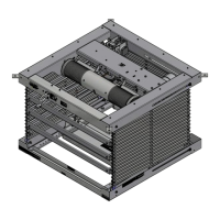
The Scissor Lift may be installed in a variety of ways; recessed above the ceiling, or suspended below the ceiling. The lift should be supported by four
⁄
" threaded
mounting rods or bolts with locking nuts.
If ceiling recessed, the entire unit
(including the projector)
should set approximately 1½" above the finished ceiling in its “stored” position. The threaded rods should pass
through the corner mounting flanges and be secured by nuts above and below. The unit should then be guy wired or blocked to prevent swinging.
Please Note: Scissor Lift must be installed in accordance with the requirements of the Local Building Codes, the Canadian Electrical Code
(CEC)
, CAN/CSA C22.1 and
the National Electric Code
(NEC)
, NFPA 70, as required. An appropriate disconnect device shall be provided as part of the building installation.
All installations should observe the following guidelines:
1.
Installer must ensure that all fasteners and supports are of adequate
strength to securely support Lift and projector. Hardware structure
should be able to hold at least four
(4)
times the combined weight of the
lift, projector, housing, closure, and ceiling material attached to closure.
2.
Fastening methods must be suitable for mounting surface, and securely
anchored so that vibration or abusive pulling on unit will not weaken
installation.
3.
Bottom of unit must be unobstructed after installation. Sufficient
clearance must be allowed below projector or optional ceiling closure.
4.
Do not use unit to support adjacent ceiling, light fixtures, etc.
CAUTION:
BEWARE OF PINCH POINTS!
5.
Do not complete the ceiling below unit until electrical
connections have been completed and unit has been
operated successfully.
6.
Use slots on the projector plate and on the closure to
adjust the unit to ensure proper alignment of ceiling
closure relative to ceiling opening.
CAUTION: DO NOT hang from, "ride," or pull down on
the unit. This could create a failure and cause damage
and/or injury.
Section 2 - Operation
•
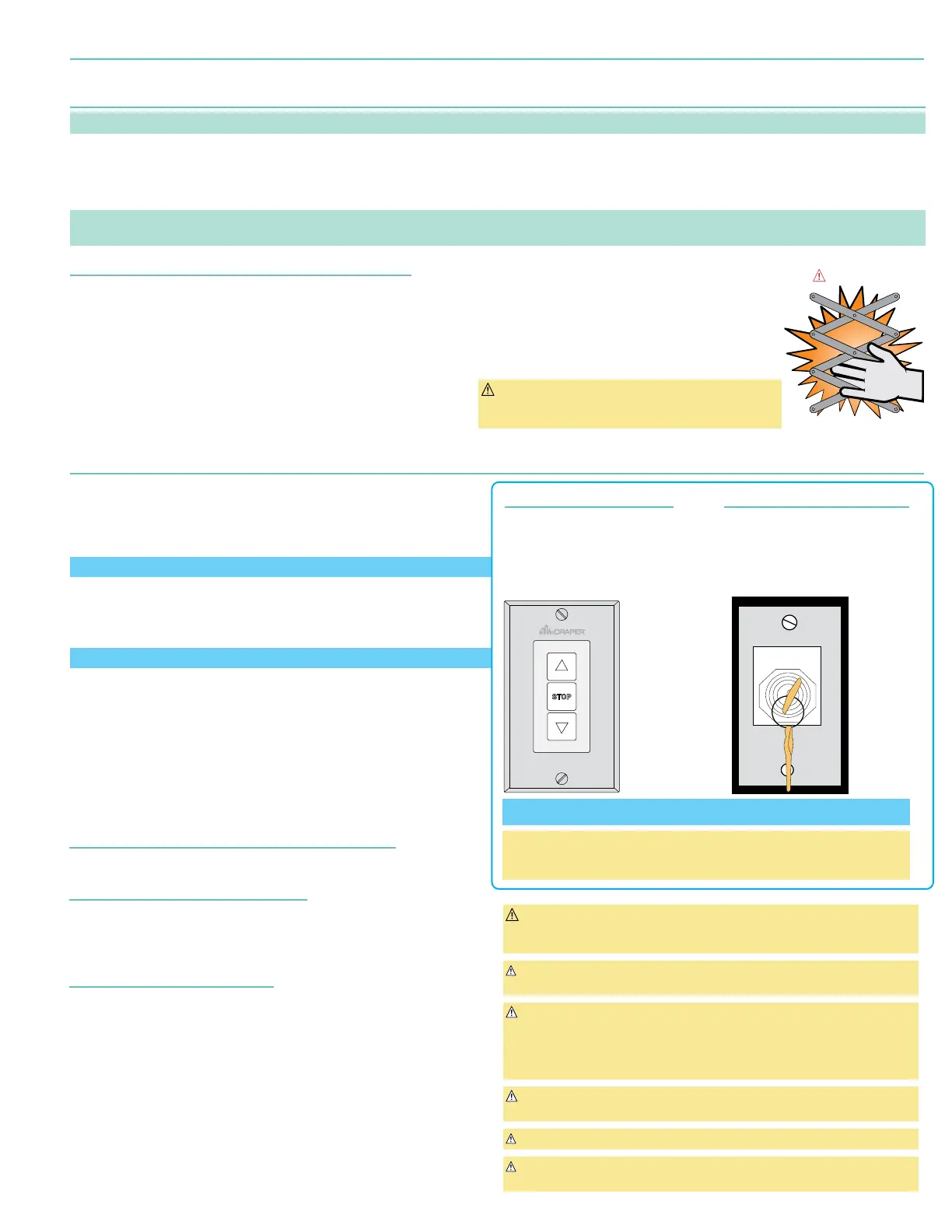
Lift Low Voltage Control - LVC-S - 121225
(Included)
:
3-button UP-STOP-DOWN switches stop at any point desired and operate
in any sequence. Factory adjusted limit switches automatically stop lift when
fully up or fully down. Installer should incorporate an all-pole disconnect in
fixed wiring available with RF or IR remote.
Used WITH SP-KSM - Key Switch - 121022 to program Scissor Lift.
•
Key Operated Switch - SP-KSM - 121022
(Included)
:
Key-operated power supply switch controls power to lift and switches. When
"off", switches will not operate lift. Key may be removed from switch in either
"on" or "off" position.
Used WITH LVC-S - 121225 to program Scissor Lift.
•
RS232 / RS485- Serial communication and network communication
optionally available. Draper GUI Available for Download.
1.
Before operating or testing the unit, make sure the packaging has been
removed from the unit. Remove the corrugated block from the cardboard
sleeve
(bottom-most packaging material)
, then collapse the sleeve and remove it,
along with the rest of the packaging.
2.
When unit is first operated, be cautious! If unit fails to operate properly, press
“STOP” and recheck electrical connections before proceeding.
Cycle unit down and up several times to confirm satisfactory operation
CAUTION: When operating for the first time, cycle unit down and up several
times to confirm satisfactory operation. Be prepared to cut POWER if
necessary.
Caution: Do not pull on or touch safety belt when unit is in motion. If belt
locks, the cables will unspool.
WARNING: To prevent operation by unauthorized persons the locking
switch cover MUST be installed over the 3-button wall switch for
installations where the lift show position will descend to a height less than 8
feet above the floor. The actuating switch controls shall be located within
sight of the projector lift.
WARNING: To prevent risk of injury, verify that no person is in the vicinity of
the device before raising or lowering.
Caution: Obstructing bottom pan may cause cables to unspool.
Caution: Do not operate Scissor Lift without a minimum of 15 lbs. of weight
attached to the pan. Operating without weight may cause cables to unspool
Both switches are required for programming
Additional momentary switches or control systems using dry contact closure,
can be connected to the switch cables, or in conjunction with the provided
switches, for multiple station control.
LVC-S
SWITCH
121225
Up &
Show
SHOW POSITION CONTROL
One three-button switch with "UP,
"DOWN, and "STOP" buttons is
provided to operate lift between
closed and show position. Using
installer supplied cable, connect
switch to "WALL" port on lift.
SP-KSM
KEY SWITCH
121022
UP
DOWN
OFF
Service
SERVICE POSITION CONTROL
One momentary key switch is provided
to operate lift to service position. Using
installer supplied cable, connect switch
to "KEY" port on lift.
Low Voltage Trigger
(Voltage Range: 3 - 28 VDC - Non polarized)
Input provided for Low Voltage Trigger from projector.
Optional Infrared Control - PN: 300349
If ordered, a 3-button transmitter with "UP", "STOP" & "DOWN". IR eye is provided.
IR eye connects to IR port on lift and the eye must be installed with line of sight for
transmitter. Transmitter will operate lift between CLOSED & SHOW positions only.
Optional RF Control - PN: 121226
If ordered, a three-button transmitter with "UP", "STOP", and "DOWN" is provided.
The RF transmitter will need to be learned to the control board in the lift.
To Enter Pairing Mode:
Press and HOLD the "RF Pairing" button, on the LVC-V, for 3 seconds.
The LED will flash for Approx. 15 Seconds, indicating remote is Pairing Mode.
To Learn Remote:
While LED is flashing, Press and HOLD the program button on back of transmitter
for 1 second. The LED will stop flashing.
To Reset: Press and HOLD the "RF Pairing" button for 7 seconds.
LED with begin to flash.
Exit Pairing Mode:
Press and HOLD the "RF Pairing" button for 1 second. The LED stops flashing.
page 3 of 8
Scissor Lift - SLX 115V