Section 11 - Electrical Connections
Lift operates on 115V, 60 Hz. current. 14 amps current draw
(2 amps for lift, 12 amps for Outlet)
Lift ships with internal wiring complete and control switch
(es)
fully boxed.
Wire to connect lift to switch
(es)
and switch
(es)
to power supply should be furnished by installer.
Please Note: Lift must be installed in accordance with requirements of Local Building Codes, Canadian Electrical Code
(CEC)
, CAN/CSA C22.1 and National Electric
Code
(NEC)
, NFPA 70. An appropriate disconnect device shall be provided as part of building installation.
CAUTION: All operating switches should be "off" before power is connected.
A junction box is provided for field connections. Unit ships with internal lift wiring complete. Use switch to lower lift and remove packing. Remove temporary wiring and
complete permanent wiring to electricity and to switches. Wire to connect unit to power supply and to switches should be furnished by installer. Connections should be
made in accordance with wiring diagram. Lift should be operated and checked prior to installing projector and/or optional ceiling closure.
Section 13 - RS232 and RS485 Serial Port Protocols
Sending Lift Commands
START ADDRESS COMMAND END
1 Char
2 Chars 1 - 6 Chars 1 Char
L
XX YYYYYY !
XX = Decimal motor group address with range from 01 to 32.
Note it always has to be 2 characters,
so a 0 has to precede 1 digit addresses.
YYYYYY = command from the following table:
EXAMPLES:
COMMAND ACTION
L01R!
Move
Channel 1 to Fully Retracted.
L11E!
Move
Channel 11 to Fully Extended.
COMMAND ACTION
E
FULLY EXTEND
R
FULLY RETRACT
S
STOP
SP1
Go to FIRST show position
SP2
Go to SECOND show position
P
PREVIOUS show position
N
NEXT show position
ADDSP
ADD show position
DELSP
DELETE show position
ID
Identify channel
SET
SET splitter board channel
ADD
ADD a communication channel (Setting main board)
DEL
DELETE a communication channel (Setting main board)
FS1
Restore MAIN BOARD to Factory Settings
FS2
Restore SPLITTER BOARD to Factory Settings
FS0
TILT to PREVIOUS STOP
GETFV1
Get MAIN BOARD Firmware Version Number
GETFV2
Get SPLITTER BOARD Firmware Version Number
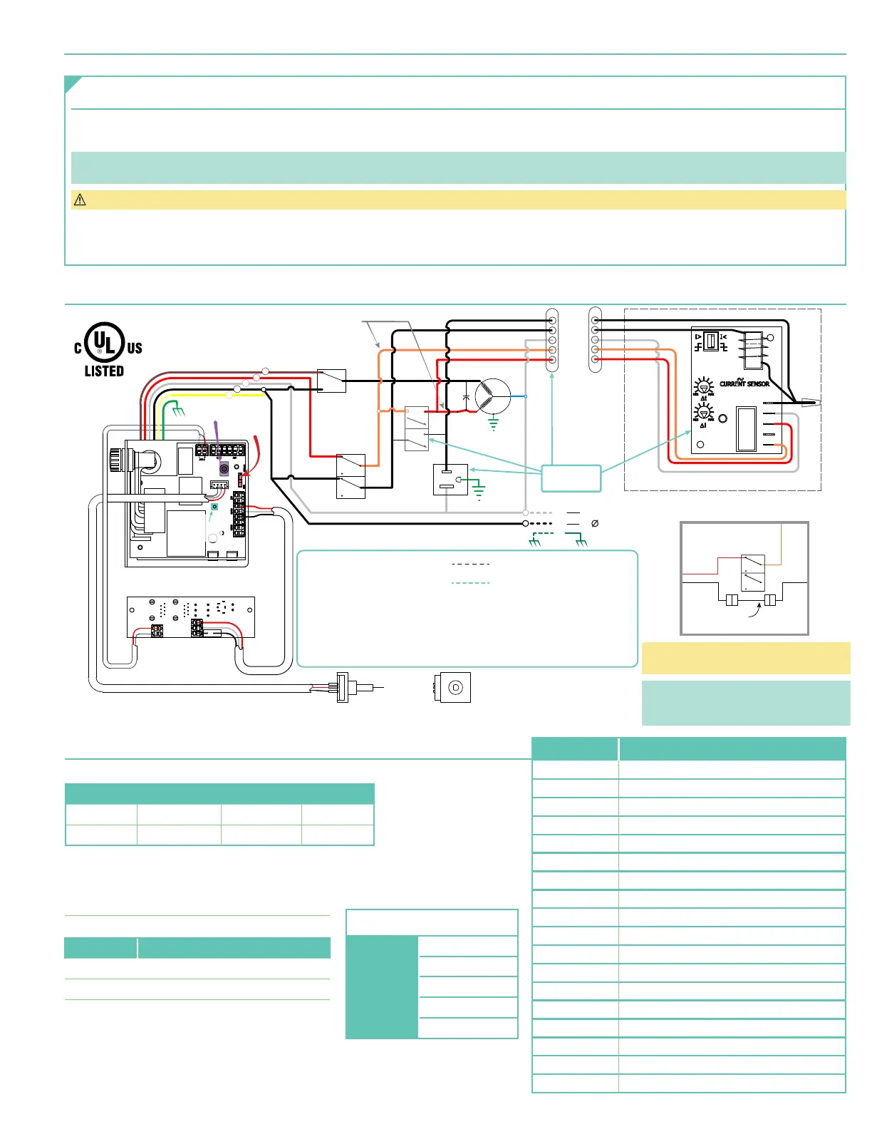
Section 12 - Wiring Schematic
RD
WH
BK
RD
WH
BK
WH
WH
MOTOR
N
GN
ENCODER
BK
BL
RD
BK
BK
OR
BK
RDRD
OR
BK
BK
BK
UP
DOWN
RUN CAP
45 MFD
NC
NC
NC
RD
WH
BK
RD
WH
RDBK
WH
GN/YL
COM
N.O.
N.C.
AC
AC
+
-
V in
A
B
GND
BK
BK
WH
OR
RD
BK
BK
WH
OR
RD
DOWN
Limit Switch
WH RD
BK
WH
RD
OR
GN/YL
UP
Limit Switch
Optional Delay Assembly
BK
BN
RD
WH
BK
YL
Delay Switch
(on position)
RD
WH
A
B
GND
BK
115Vac, 12A
50-60 Hz OUTLET
NOTES:
1. When the Optional Delay Feature is installed the Delay Switch must
be in the "Delay On" position for normal operation.
2. If the Optional Delay Feature is installed and the "Show" position requires adjusting
the "Delay Switch" must be switched to "Off" while adjusting the show position
3. Refer to the "Adjusting" section on page 4 of these instructions
for information on how to adjust the "Show" position.
Dashed wiring by electrician
Low voltage wiring by others
115VAC
Power Supply
MODE
SWITCH
2 CONDUCTOR CABLES
ATTACHED TO
REAR SCISSOR
ENCODER CABLE
ENCODER CABLE
IR EYE
RF
PAIRING
Attached to
lower pan
RD
BKBK
OR
Up
Limit
Switch
NC
NC
BK
Jumper*
ALTERNATE ‘UP’ LIMIT SWITCH WIRING
COM Port Settings:
Port Speed: 9600 baud
Data Bits 8
Parity NONE
Stop Bits 1
Flow Control X On / X Off
*Black
(BK)
Jumper wire is located in the
plastic sleeve with these instructions.
NOTE : Jumper CANNOT be used when lift
is installed in Environmental Air Space
Housing and Optional Ceiling Closure
page 7 of 8
Scissor Lift - SLX 115V