Do you have a question about the Draytek VigorSwitch FX2120 and is the answer not in the manual?
The DrayTek VigorSwitch FX2120 is an L2+ managed switch designed for robust network environments, offering advanced features for efficient data management and connectivity. This quick start guide provides essential information for setting up, configuring, and maintaining the switch, ensuring optimal performance and reliability.
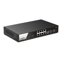
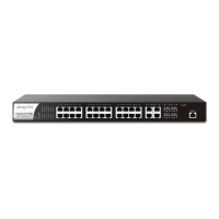
The VigorSwitch FX2120 serves as a central hub for network connectivity, providing 12 ports for fiber connections, specifically 10Gbps SFP ports. As an L2+ managed switch, it offers sophisticated control over network traffic, enabling administrators to segment networks, prioritize data, and enhance security. The switch supports various network protocols and management capabilities, making it suitable for demanding business and enterprise applications where high-speed and reliable data transfer are critical. Its managed capabilities allow for detailed configuration and monitoring, ensuring that network resources are utilized effectively and securely. The device is designed to handle significant data loads, making it ideal for environments requiring high bandwidth and low latency.
The VigorSwitch FX2120 is designed for straightforward installation and configuration. The package content includes the VigorSwitch FX2120 unit, a quick start guide, rack mount kit (brackets), and a DAC Cable. Power cords are provided based on the country of installation (UK-type, EU-type, USA/Taiwan-type, AU/NZ-type).
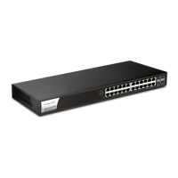
Network connection involves inserting the connector into any of the 12 SFP ports and pulling the release latch to remove it. For rack-mounted installation, the rack mount kit is fastened to both sides of the VigorSwitch using specific screws, and then the switch is installed onto a 19-inch chassis using four other screws.
The front panel features LEDs for monitoring various statuses:
Before configuring the switch, a physical path must be set up between the switch and a PC. This involves inserting one end of the DAC cable connector into an SFP slot (port 1-12) on the switch and the other end into the network card on the PC. If directly connecting a PC to the switch, the PC's subnet mask must be configured to match the switch's default subnet mask. The default IP address of the switch is 192.168.1.224, with a subnet mask of 255.255.255.0. DHCP Client is enabled by default. The default username and password for accessing the switch's web interface are "admin".
After configuring the correct IP address on the PC, users can open a web browser and access the switch's IP address. The home page of the VigorSwitch will then be displayed, allowing for comprehensive management and monitoring of the device. The web interface provides a dashboard with an overview of device status, including device name, IP address, firmware version, uptime, MAC address, system time, and resource usage (CPU, memory, cache). It also displays port status, recent activities, ONVIF surveillance, and IP conflict status.
The VigorSwitch FX2120 is designed for long-term reliability, but proper maintenance and support are crucial.
If the switch encounters issues that cannot be resolved through troubleshooting, users are advised to contact their local supplier for assistance. Technical support is available via email at support@draytek.com for any questions or concerns.
DrayTek encourages users to register their Vigor device online at https://myvigor.draytek.com. This ensures access to support and updates.
DrayTek continuously evolves its technology, and all switches receive regular upgrades. Users should consult the DrayTek website (https://www.draytek.com) for the latest firmware, tools, and documentation to keep their device updated and secure.
DrayTek provides a two-year warranty from the date of purchase, covering defects in workmanship or materials. The purchase receipt serves as proof of purchase. During the warranty period, DrayTek will repair or replace defective products or components at its discretion, without charge for parts or labor. Replacements may be new or re-manufactured functionally equivalent products. The warranty does not cover modifications, misuse, tampering, damage from acts of God, or abnormal working conditions. Bundled or licensed software from other vendors is also excluded. Defects that do not significantly affect usability are not covered. DrayTek reserves the right to revise manuals and online documentation without prior notification.
The device complies with Federal Communication Commission (FCC) regulations for Class A digital devices, ensuring reasonable protection against harmful interference in residential installations. It generates, uses, and can radiate radio frequency energy. If interference occurs, users are advised to reorient the receiving antenna, increase separation between equipment and receiver, connect the equipment to a different circuit, or consult a dealer/technician. The device complies with Part 15 of the FCC Rules, meaning it may not cause harmful interference and must accept any interference received. Changes or modifications not expressly approved by the responsible party could void the user's authority to operate the equipment.
The VigorSwitch FX2120 also adheres to EU and UK regulatory standards, including EMC, Low Voltage, and RoHS directives, with specific versions and issue dates for standards like EN 55032, EN 61000-3-2, EN 61000-3-3, EN 55035, EN 62368-1, and EN IEC 63000:2018. Declarations of Conformity are provided for both EU and UK regulations, signed by Calvin Ma, President of DrayTek Corp.
| Power over Ethernet (PoE) | Yes |
|---|---|
| MAC Address Table Size | 8K |
| Power Input | 100-240V AC, 50/60Hz |
| Operating Temperature | 0°C to 45°C |
| Management | Web-based, CLI, SNMP |
| Jumbo Frame | 9KB |
| Storage Temperature | -40°C to 70°C |
| Humidity | 10% to 90% non-condensing |