The VigorSwitch P2540xs is an L2+ Managed Switch designed for network connectivity and power delivery, particularly for PoE-enabled devices. This Quick Start Guide, version 1.1 with firmware V3.7.4, dated September 30, 2022, provides essential information for installation and configuration.
Function Description:
The VigorSwitch P2540xs serves as a central hub for network connections, offering both standard Ethernet and Power over Ethernet (PoE) capabilities. As an L2+ managed switch, it provides advanced Layer 2 features and some Layer 3 functionalities, allowing for more sophisticated network management, traffic control, and security. It is designed to supply power to PoE devices over twisted-pair cables, eliminating the need for separate power sources for these devices. The switch supports various network devices, including PCs, servers, network printers, IP phones, IP cameras, and wireless access points (APs). Its management interface is accessible via a web browser, providing a user-friendly way to configure and monitor network settings. The device also includes a console port for telnet command control, offering an alternative method for advanced configuration.
Important Technical Specifications:
- Ports:
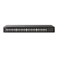
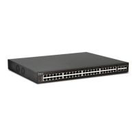
- 48 x GbE RJ45 ports (Port 1-48) with PoE capabilities. These ports support Ethernet connection and can supply PoE power depending on the connected device.
- 6 x SFP+ ports (Port 49-54) for 10G/1000M fiber connections.
- PoE Power Output:
- IEEE 802.3af Max. 15.4W Output Supported
- IEEE 802.3at Max. 30W Output Supported
- PoE Power Budget: 400 Watts (Max)
- Power Inlet: AC input (100~240V/AC, 50/60Hz)
- Firmware Version: V3.7.4
- Loader Version: 2.2.0
- Revision: 023db45
- Build Date: 2022-07-07 09:24:23
- System Up Time: Displayed in days, hours, minutes, and seconds (e.g., 19 days 20:16:24)
- Operating Temperature Range: 0 to +45 Celsius.
- Default IP Address: 192.168.1.224
- Default Subnet Mask: 255.255.255.0
- Default Gateway: 192.168.1.254
- Default Username/Password: admin/admin
- Compliance:
- EU Declaration of Conformity: EMC Directive 2014/30/EU, Low Voltage Directive 2014/35/EU, RoHS 2011/65/EU. Standards include EN 55032 (2015+AC:2016 Class A), EN 61000-3-2 (2014 Class A), EN 61000-3-3 (2013+A1:2019), EN 55035 (2017), EN 62368-1 (2014+A11:2017), EN IEC 63000:2018.
- UKCA Declaration of Conformity: The Electromagnetic Compatibility Regulations 2016 (SI 2016 No.1091), The Electrical Equipment (Safety) Regulations 2016 (SI 2016 No.1101), and The Restriction of the Use of Certain Hazardous Substances in Electrical and Electronic Equipment Regulations 2012 (SI 2012 No. 3032). Standards include EN 55032 (2015+A1:2016 Class A), EN 61000-3-2 (2014), EN 61000-3-3 (2013+A1:2019), EN 55035 (2017), EN 62368-1 (2014+A11:2017), EN IEC 63000:2018.
- Federal Communication Commission Interference Statement: Class A digital device, Part 15 of the FCC Rules.
Usage Features:
- Network Connection:
- Connect PoE devices (e.g., IP phones, IP cameras, APs) to ports 1-48 using Cat. 5e twisted-pair cables. The switch automatically supplies power.
- Connect non-PoE devices (e.g., PCs, routers, printers, notebooks) to any port using standard 'straight through' twisted pair cables.
- Utilize SFP+ ports (49-54) for high-speed fiber connections (10G/1000M).
- LED Indicators:
- Monitor (Red/Off): Indicates system failure (overheating, wrong voltage) or normal operation.
- Alert (Blinking Green/Off): Shows if PoE power budget is over (>) 80% or under (<) 80%.
- SYS (On Green/Blinking Green/Off): Indicates system readiness, booting process, or power off/malfunction.
- PWR (On Green/Off): Shows if the device is powered on/running normally or not ready/failed.
- PoE Port 1-48 (On Green/Off): Indicates if PoE power is supplied or not.
- Port 1-48 (On Green/On Amber/Blinking/Off): Shows connection speed (1000Mbps/10/100Mbps), data transmission, or disconnected/failed link.
- Port 49-54 (On Green/On Blue/Blinking): Shows connection speed (1000Mbps/10Gbps) or data transmission.
- Slide Switch: Toggles LED function to display either PoE connection status (right) or LAN port connection status (left).
- Software Configuration:
- Access the web-based management interface by connecting a PC to the switch and opening a web browser to the switch's IP address (default: 192.168.1.224).
- Login with default credentials (admin/admin).
- The home page provides a dashboard with device information (model, firmware, loader, revision, build date, system time, uptime) and system information (CPU, memory, cache, PoE usage, temperature, voltage).
- The interface allows for comprehensive management of switch LAN, ONVIF surveillance, VLAN routing, security, ACL, QoS, PoE settings, system maintenance, diagnostics, and mail alerts.
- Console Port: Used for telnet command control, offering an alternative for advanced configuration and troubleshooting.
Maintenance Features:
- Rack-Mounted Installation: The switch can be installed in a 19-inch chassis using the provided rack mount kit. Brackets are fastened to the switch with specific screws, then the switch is mounted to the chassis with four other screws.
- RST Button: Restores the switch to its default settings.
- Firmware & Tools Updates: DrayTek regularly upgrades switches. Users are advised to consult the DrayTek website (https://www.draytek.com) for the newest firmware, tools, and documents.
- Customer Service: For issues that cannot be resolved, users can contact their local dealer or email support@draytek.com.
- GPL Notice: The product uses software licensed under the GNU GENERAL PUBLIC LICENSE. Source codes are available for download at http://gplsource.draytek.com.
- Warranty: A two-year warranty is provided to the original end-user, covering defects in workmanship or materials from the date of purchase. The warranty does not cover modifications, misuse, tampering, acts of God, or abnormal working conditions.
- Environmental Disposal: Users are advised to follow local regulations for environmental conservation when disposing of the switch.
- Safety Instructions:
- Read the installation guide thoroughly.
- Only authorized and qualified personnel should repair the switch. Do not attempt to open or repair it yourself.
- Avoid placing the switch in damp or humid places.
- Use the switch in a sheltered area within the specified temperature range (0 to +45 Celsius).
- Do not expose the switch to direct sunlight or other heat sources.
- Do not deploy LAN cables outdoors to prevent electronic shock hazards.
- Keep the package out of reach of children.