-10-
Operation
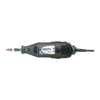
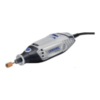
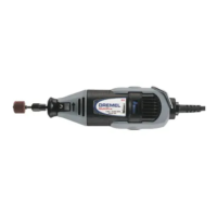
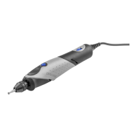
WORKSTATION IS DESIGNED FOR USE
ONLY WITH DREMEL ROTARY TOOL
MODELS 100, 200, 275, 285, 300, 395, 398,
400, 800, 3000, 4000, 8100, 8200, 8220, 4200
and 4300.
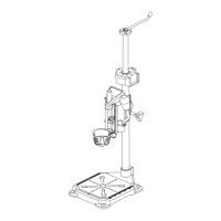
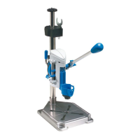
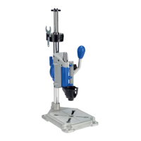
Your Dremel Workstation 220 will convert
rotary tools to a drill press for drilling, to a tool
holder for sanding or polishing, or to a flex
shaft tool stand.
Workstation is for use
with only one tool at
time. Do not hang a tool on hanger assembly
when another tool is mounted in the press.
The Crow’s Nest tool storage (Fig. 12) will
hold the following tools:
• Drill bit set (Model 628 or 631)
• Rotary tool wrench
• Mounting wrench
• Bits with shank size less than or equal to 1/8"
• Rotary tool collets
(Models 480, 481, 482, 483)
Drill Press
Instructions
NOTE: The drill bits are held in the tool by a
collet system or Dremel 3-jaw chuck. The bit
may be installed before or after the rotary tool
is installed in the drill press.
1. Insert and secure the drill bit into Dremel
rotary tool. See your rotary tool manual for
detailed instructions (Fig. 13).
2. The Depth Stop is used when you wish to
drill holes to a measured depth. A scale on
the press housing is provided for your
convenience.
Set the depth stop adjustment to the
desired depth and tighten depth stop lock
knob 9D (Fig. 16). Four set screws 9E are
also provided on the depth gauge and left
side of the housing assembly (See Fig.
16). These screws allow for micro
adjustments to the action of the drill press.
Use small flathead screwdriver to tighten or
loosen the movement of the press. Be
carefull not to overtighten set screws.
3. The small Angle Lock knob 10 and large
Angle Lock knob 11 are used to secure the
tool either vertically or at a 90° angle. Tool
may be used at a 15°, 30°, 45°, 60°, 75° or
90° angle for off axis drilling applications
(Fig. 16).
Loosen the large and small knobs and
rotate the tool, then securely tighten both
angle lock knobs.
4. The Height Adjustment Lever 7 is used to
secure the press on the tube at the proper
height (Fig. 16).
Loosen the lever and move the press/tool
assembly to the desired position, then
tighten the height adjustment lever.
5. Mark the hole locations on the workpiece
For illustrations refer to pages 2 - 6
Disconnect the plug from the power source and/or the battery pack
from the power tool before making any adjustments, changing
accessories, or storing power tools. Such preventive safety measures reduce the risk of
starting the power tool accidentally.
table top. Using the corner of the workbench
is the most secure since at least 3 clamps
can be used. See Fig. 8 c.
Rotary tool installation
To install rotary tool
- Remove nose cap from rotary tool.
- Insert the rotary tool into drill press unit 9
and secure it in place by tightening the
clamp nut 9C with clamp wrench 5 (Fig. 10).
NOTE: Model 398 mounts with shaft lock S
to the back and cord to the right. Models
400 and 800 mount with shaft lock S to the
right.
NOTE: When clamping rotary tool in holder,
make sure tool is seated properly and vent
openings are not covered.
- Insert power cord into the cord clips 9D (Fig.
11). This will keep power cord away from
the work area.
NOTE: Make sure there is sufficient slack to
keep the cord from being pulled tight when
the full stroke of the drill press is conducted.
 Loading...