Connectors and Status Indicators
Front Panel
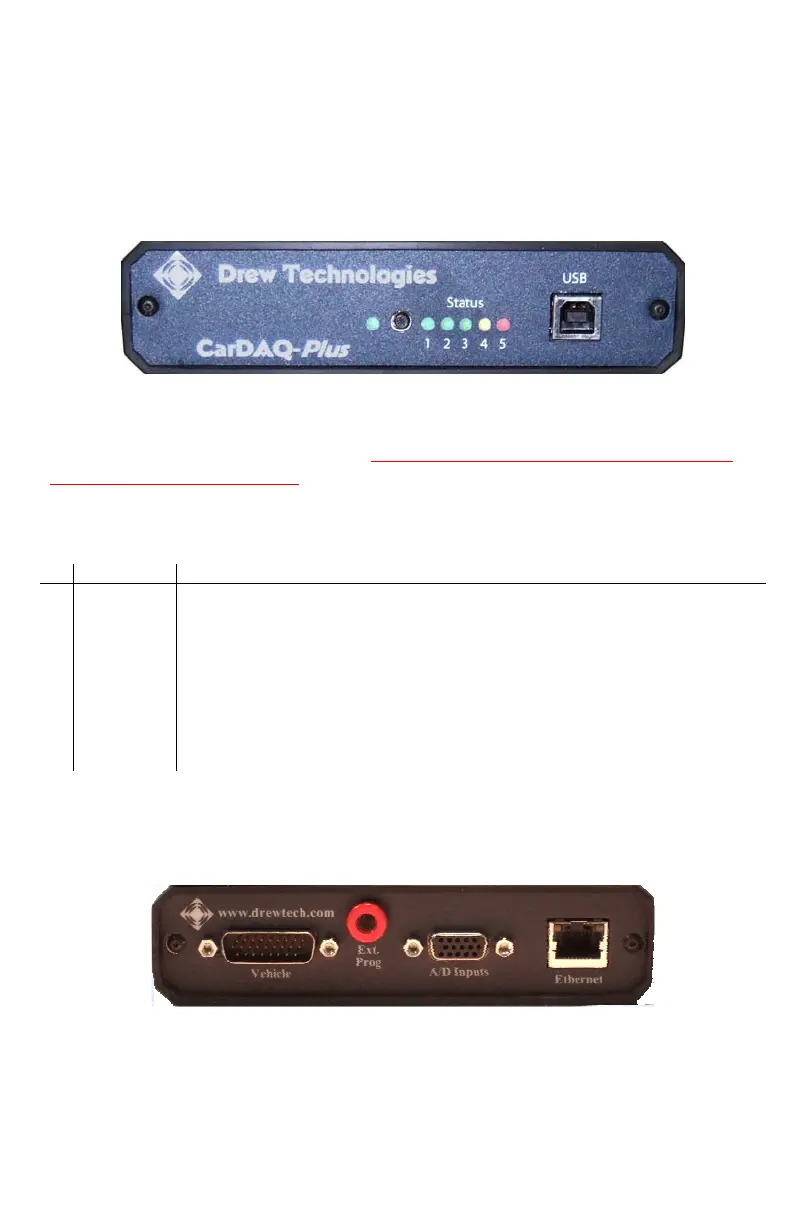
The front panel of the CarDAQ-Plus holds the USB connector for
connection to a PC, status lights, and the reset button. The 6 status
lights on the front panel of CarDAQ-Plus are useful for troubleshooting
the CarDAQ-Plus connection to a PC.
Figure 1: CarDAQ-Plus with USB
The #4 yellow warning light indicates that the CarDAQ-Plus is
communicating with the vehicle. Do not disconnect anything while the
yellow light is illuminated! Refer to Table 1 for a description of the other
status lights.
Table 1: Status lights on the front panel of CarDAQ-Plus
# Light Description
Power Power (Solid Green)
1
Ethernet Green indicates a good connection directly to a PC or to an existing
Ethernet network.
2
USB Green indicates a good USB connection. The PC has identified and
configured CarDAQ-Plus properly.
3
N/A Available for future expansion.
4
Vehicle Yellow warns that CarDAQ-Plus is communicating with a vehicle. Blinks
to indicate activity on the vehicle’s network.
5
Fault Red indicates a momentary network fault or a serious hardware failure.
Please call technical support for assistance.
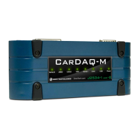
Rear Panel
Connections to the vehicle, Ethernet, analog inputs, and external
programming voltage are available on the rear panel.
Figure 2: Rear panel with vehicle, analog, and Ethernet sockets
The red external programming socket provides access to the 5-20V
programming voltage. This is used for Mitsubishi, Subaru or any other
vehicle that needs voltage on an additional connector.