For technical questions, please call 1-800-444-3353.
SAFETY OPERATION MAINTENANCESETUP
Specifications
4005695
Setup - Before Use:
at the beginning of this manual including all text under
subheadings therein before set up or use of this product.
REVENT SERIOUS INJURYREVENT SERIOUS INJUR
Make sure that the Switch is in the off
before assembling or making any adjustments to the tool.
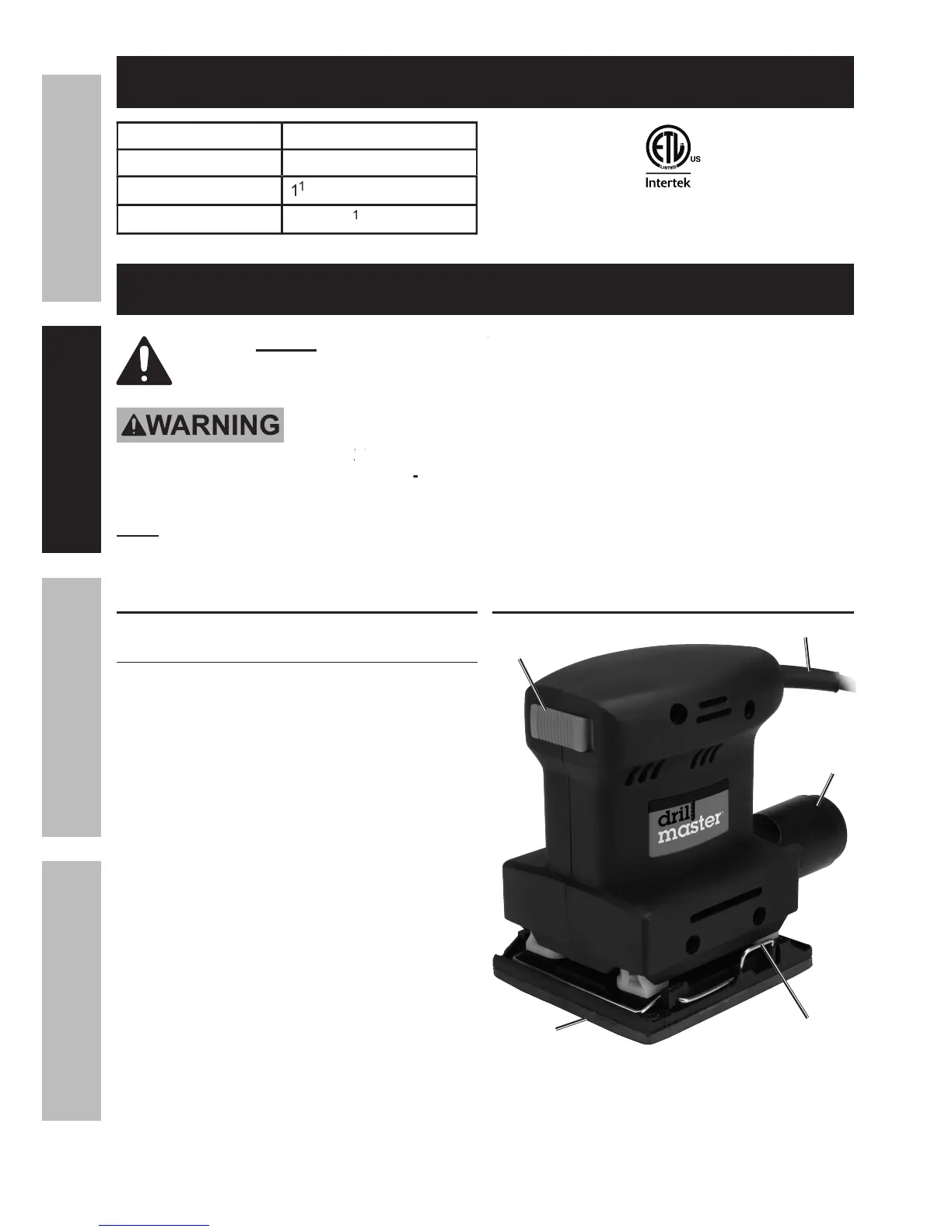
For additional information regarding the parts listed in the following
Turn the Chute (0) so that the tab on
top of the rectangular end faces up.
Snap it in place into the rectangular
shaft at the back of the Sander.
Connect a 1-1/4″ dust collection hose
from the Chute to your dust collection
system (hose and system not included).
The Dust Collection Chute (0) will only
work if the sandpaper has holes that line
up with the 6 dust collection holes in the
Backing Pad (28). (There are 4
in the Backing Pad for the