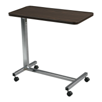
1. Table Top
2. Column Assembly
3. Trip Lever
4. 1/4-20 Bolt & Nut (1 each)
5. Bracket Top to Column
6. 1/4-12 Bolt (2)
7. Base
8. Casters with Brake
9. Casters without Brake
10. Bolt Sleeves (2)
11. Bolt Plate
12. 3/8-15 x 2” Bolts
13. Black Screw
14. Chrome Screw (Hex-Head Screw)
parts list
1. Open end of box. Slide contents out of
box. Lay on level surface. Remove base,
table top and hardware.
2. Insert column assembly (2) into top
brackets (5) as shown. Be sure the trip rod
(inside column) is fully inserted inside the
column. Align holes in column and top
bracket and install 2 bolts (6) & fasten.
3. Install trip lever (3) as shown, rounded side
facing table top. Be sure trip lever sits on
top of rod inside column. Align hole in trip
lever (3) with hole in top bracket (5) and
insert bolt & nut (4) to fasten the trip lever
& top bracket.
4. Place 2 bolts (12) through bolt plate (11) and
2 bolt sleeves (10). Place bolt assembly
into base to column.
5. Install casters (8, 9) as shown and replace
with chrome screw.
assembly instructions
CAUTION
FOR SAFETY DO NOT REMOVE BLACK SCREW
ON COLUMN UNTIL TABLE IS FULLY
ASSEMBLED AND IN A STANDING UPRIGHT
POSITION. (CHROME SCREW HEX-HEAD ON
COLUMN IS NOT TO BE REMOVED)
DO NOT REMOVE BOTTOM SCREW
operating instructions
1. To raise top to desired height, apply light
pressure upward at any point under table.
2. To lower, squeeze trip lever (3) up towards
top and push down at column to desired
height. Do not put pressure on tabletop
end that is opposite the column. Column
assembly will lock upon release of trip lever.