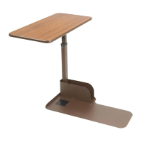
THIS TABLE IS TO BE USED WITH
HEAVIER CHAIRS AND COUCHES.
INCORRECT POSITIONING OF
TABLE BASE (#7) UNDER THE
CHAIR OR COUCH MAY RESULT
IN THE TABLE TIPPING OVER.
(REF. ASSEMBLY STEP 1)
assembly instructions
CAUTION--SPRING LOADED ASSEMBLY
Do not remove the black shipping screw
before completing assembly steps 1- 5.
Removing the shipping screw before this can
result in personal injury and spring damage.
PRODUCT IS NOT TO BE USED AS A LIFT
ASSIST OR TO HOLD MORE THAN 25 LBS.
Tools Necessary For Assembly:
Phillips Screwdriver
(2) 7/16” Wrenches
FIGURE 1
FIGURE 2
FIGURE 3
TO ELEVATE THE TABLE:
Push upwards at any position on the underside
of the top, until the top has reached the desired
height.
TO LOWER THE TABLE:
Squeeze the trip handle up and push the top down
to the desired height. The table will operate best
if the downward pressure is placed at the column
end of the top.
Occasional application of light oil lubrication
between the inner and outer columns will help
keep your Table operating smoothly. Penetrating
oils with rust inhibitors are recommended.
The table will swing a full 360º around on the base
to be used as an end table or a lap tray as needed.
operating instructions
1. Place the base (#7) under the le side of chair
with the magazine rack opening facing the
rear of chair. Place the front le leg of the
chair on the positioning pad (#8) located near
the magazine rack.
2. Stand the Column (#6) on end, making sure
the Trip Rod is visible in the rectangular tube
but not protruding out of the top, as shown in
Fig. 1. If necessary, shake the Column (#6) until
the rod drops.
3. Insert Trip Handle (#4) into the Column (#6)
with the rounded side up. Be sure that the
Trip Handle (#4) rests on top of the rod inside
the Column (#6). Fig. 1
4. Place the Top (#1) on a flat surface, with the
Top Bracket (#9) facing upward. Then, while
holding the Trip Handle (#4) in place so it
doesn’t fall out, insert the Column (#6) into the
Top Bracket (#9). Align the holes in the
Column foot (#6), the Trip Handle (#4) and the
Top Bracket (#9). Install both bolts (#2) and
both nuts (#5) thru these aligned holes with
the two (2) 7/16” wrenches. Fig. 2
5. Pick up the Top (#1) and Column (#6) and place
over the round tube on the Base (#7) inside of
the magazine rack. Be sure the Column (#6)
has dropped down all the way!
6. Remove the black shipping screw in the
column and replace it with the zinc plated
screw (#3), using a Phillips screwdriver. Fig. 3
Rev.6.05.15.14