7. Electrical connections
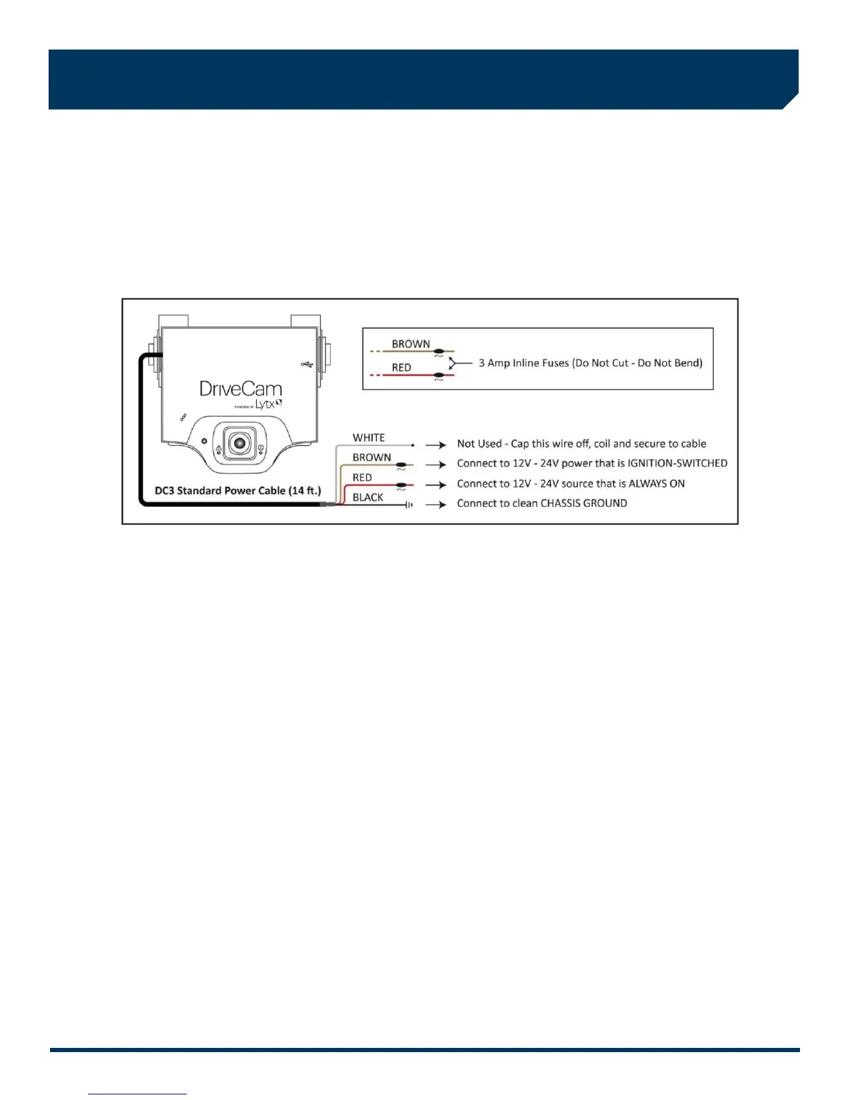
The black, red and brown wires are the three required connections for the VER to function. The red wire provides primary
power and must be connected to a continuous power source. The brown wire is an ignition-sense, used by the VER to
activate the IR Illuminator (page 8) when the vehicle ignition is switched on. The black wire is ground.
A) Find a suitable location to make electrical connections (usually under the dashboard or vehicle electrical panel).
B) Connect the power cable to the vehicle as described below.
C) Test the connections in steps 8 and 9 before finalizing the connections.
Connecting the RED WIRE to a 12V-24V power source that is ALWAYS ON
The VER requires a power source that is not controlled by the key nor any other device or switch. This connection is
usually made just after the fuse box on the battery-side of any vehicle control modules. Use a voltmeter to make sure the
circuit provides continuous 12V or 24V power when the key is removed from the ignition and all lights, devices and
switches are off. Test this connection in Step 9.
Current Draw: If you’re tapping into an existing vehicle wire, make sure it can handle the additional current draw of the
VER. A wire that reads 12V on a voltmeter may not necessarily be able to supply enough current to the
existing circuit and the VER. The gauge of wire being tapped into provides a good indication. A larger
gauge wire is often the best choice, but make sure to test it with a load.
Connecting the BROWN WIRE to a 12V-24V power source that is IGNITION-SWITCHED
This connection senses when the ignition is switched on. This requires a power source that is “on” only when the key is
turned all the way forward to the “on” position and when the engine is running. It’s very important that this is connected
properly. Test this connection in Step 10.
Common Error: This connection is often (mistakenly) made to a modulated circuit – one that comes out of a computer
control module running some subsystem in the vehicle – which can give false ignition on/off signals.
To avoid this, make sure to connect this wire to a circuit that is on the battery side of any modules.
Consult the vehicle wiring schematics or a local authorized dealership to obtain this information.
Extending Wires
If wires need to be extended, extend the ground wire first. If you must extend the red or brown wires, keep them as
short as possible. If the extended length exceeds 16 inches, place an inline fuse (1-3 Amp) between the extended wire
and the power connection. You may cut the Inline Fuses (shown above) and move them to the end to the extension if
needed. The gauge of wire used for the extension must be the same gauge as the power cable wires or larger.
 Loading...