18
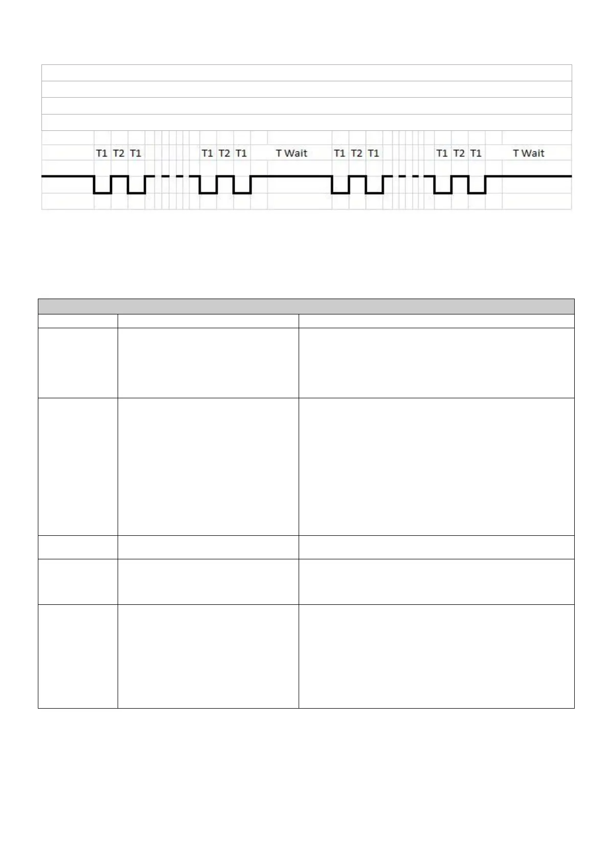
The timing chart below shows how to interface the logic with your PLC.
9.3 DIAGNOSTICS
A diagnostics table is provided below that indicates the main anomalies, the probable causes and the possible solutions.
If you were not able to solve the problem after consulting the diagnostics table, do not try to find the fault by disassembling
machine parts but contact the Dropsa technical office and report the anomalies that have been discovered, with a detailed
description.
The pump does
not deliver oil
It intakes air because the tank is empty
The intake filter is dirty or clogged
The internal fittings are loose or broken
The motor rotates backward
Restore the level in the tank and bleed the air from the system
Wash the filter with petroleum and blow with compressed air
Carefully close all the fittings, making sure there are no leaks and
replace the broken pipes.
Correctly connect the motor, inverting the direction of rotation
The pump does
not deliver oil at
the required
pressure
Pump deteriorated
Pressure control valve uncalibrated set too
low (therefore the oil returns immediately
to the tank).
Release valve damaged
Adjustment valve incorrectly calibrated
Presence of dirt in the by-pass valve
Replace the pump
Tighten the adjustment screw until oil comes out of the delivery pipe
Replace the by-pass valve
Connect a pipe that is approx. 30 cm long to the pump outlet with a
pressure gauge applied to the free end. Adjust the valve by turning
the screw and reading the corresponding pressure value on the
pressure gauge
Remove the components and wash them with petroleum. Before
reassembling the components, check the wear status of the O-ring.
Replace the entire assembly if necessary
Line pressure not
released
Control valve with irregular operation
Disassemble and clean the by-pass valve, replace the valve if
necessary
Emptying of the
main system line
during the pause
time
Pump or system outlet fittings loosened
Non-return or release valve dirty
Tighten the fittings
Disassemble and clean the by-pass valve, replace the valve if
necessary
Lubrication cycle
not performed
Cycle control pressure switch calibration
pressure not reached due to:
Line pipe broken or loose fittings
Pressure switch calibrated higher than the
pump
The pump does not deliver oil at the
required pressure
The pump does not deliver oil
Replace the pipe - fully tighten the fittings
Correctly calibrate the pressure switch
See the diagnostics table
See the diagnostics table
Alarm code= number of (T1+T2)
T1= 500ms = alarm contact activation time
T2= 500ms = alarm contact deactivation time
TWait= 2000ms= pause time before repetition of same alarm code