4
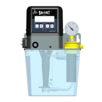
5. PUMP COMPONENTS
Following main components of the pump:
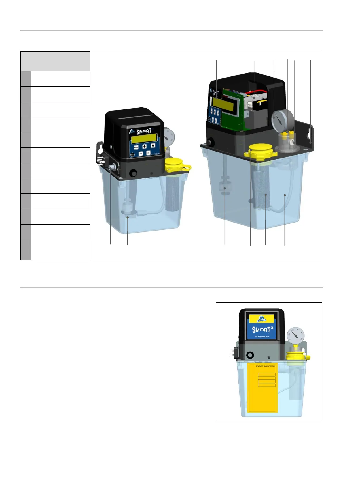
6. VERSIONS
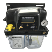
6.1 MANUAL VERSION
This version is not equipped with an integrated control system. All control and
monitoring of the pump is done by an external control system or PLC. This is
typically the configuration used for Machine Tools factory fit.
The Pump is equipped with connection plate located under the pump cover
where all electrical connections are concentrated (motor, minimum level,
pressure switch). On the front face of the pump, there is a button to activate a
lubrication cycle manually. When pressed, the button closes a contact. This
signal is fed back to the external PLC control that will then run a lubrication
cycle.
The level and Pressure switch can be wired either in series or in parallel
depending on the choice of connector used by the host PLC which will
determine alarm or low-level condition that may be present.
Control board
(for automatic versions)