Page 4 For technical questions, please call 1-888-866-5797. Item 63892
Installation Instructions
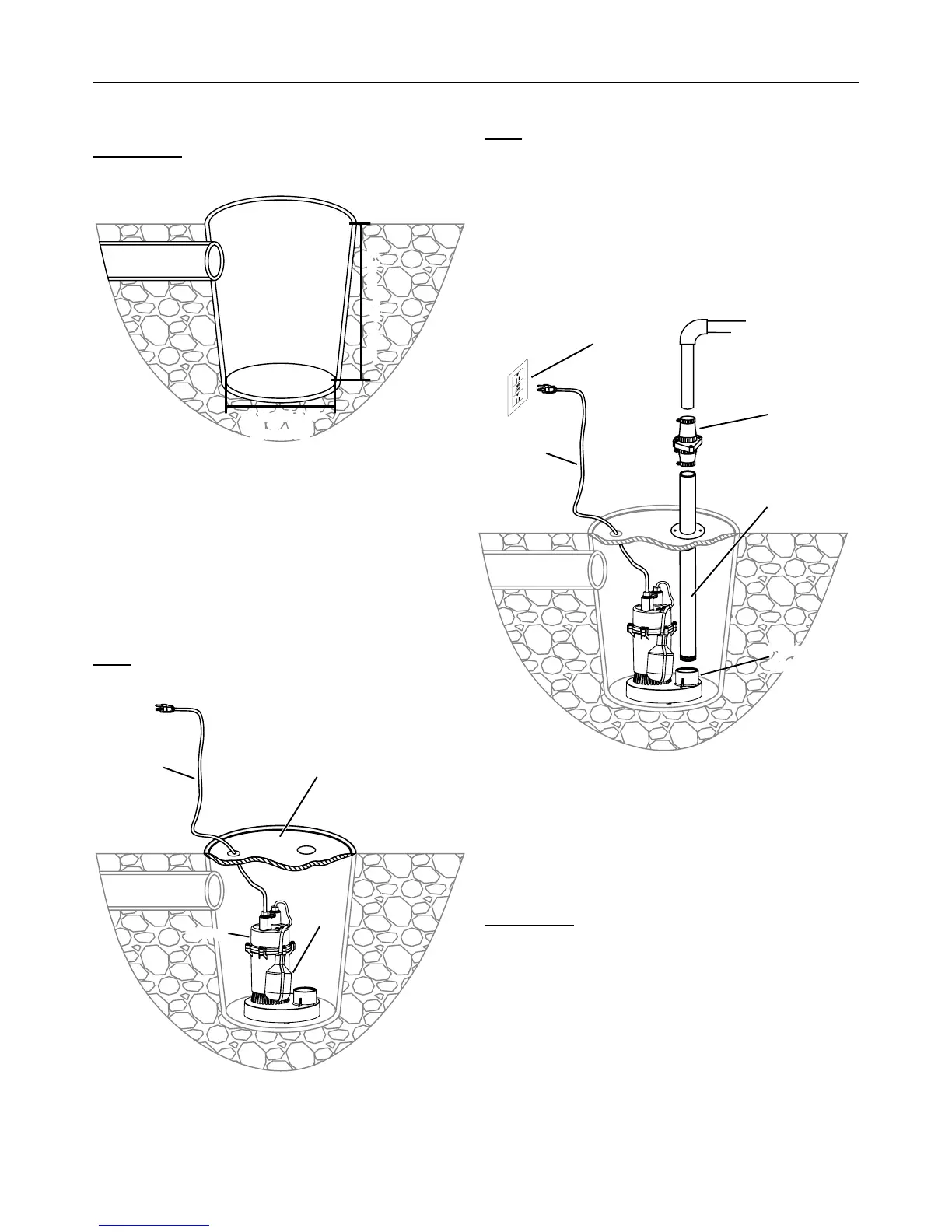
1. Construct a basin that is at least 18" deep
and at least 14" in diameter.
IMPORTANT: Sump basin must be a minimum of
14 inches in diameter for Pump to function properly.
at least 14"
diameter
at least 18" deep
Sump
Basin
Inlet Pipe
Figure A: Sump Basin
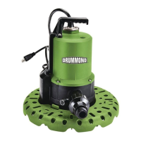
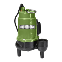
2. Position Pump on solid surface.
When positioning make sure the Float Switch is
away from the inlet pipe and at least 1 inch away
from all obstructions throughout its movement.
3. Fit a sump cover with a hole for the output pipe
and a hole for the power cord. Thread the
Power Cord through the hole, but do not plug
it in yet. Set the sump cover aside for now.
Note: The sump cover can also be
fitted with a vent pipe, if desired.
Float
Switch
Pump
Pump
Cord
Sump Cover
Figure B: Pump Position
4. Attach a discharge pipe to the Pump Outlet.
Note: Wrap all threaded connections
with PTFE thread seal tape.
5. To prevent excessive cycling from backflow of
water, install a check valve (not included) onto
the discharge pipe. This prevents water from
flowing back after the pump shuts off. Install
according to manufacturer’s instructions. Mount
the check valve according to check valve label
to avoid the valve flapper getting stuck.
Pump
Cord
To discharge
(away from foundation)
GFCI-Protected
Receptacle
Check
Valve
Pump
Outlet
Discharge
Pipe
Figure C: Outlet Pipe and Plug
6. Connect additional Discharge Pipe as needed
to direct the water discharge at least 3 feet
away from the foundation. Slope the discharge
pipe downward, away from the foundation.
The discharge should be kept as short as
possible with a minimum number of turns.
IMPORTANT: Do not exceed the Maximum
Head Lift @ 0 GPH Flow of the Pump.