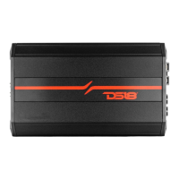
This document is an owner's manual for DS18 CANDY-X Class D Amplifiers, including the CANDY-X1B, X2B, X4B, X5B, and XXL1B models. These amplifiers are designed for mobile applications, providing high-quality stereo playback with low harmonic distortion, considerable reserve voltage, and high-temperature stability. The manual provides detailed instructions for functions, controls, and various wiring configurations.
Function Description:
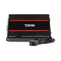
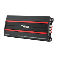
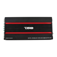
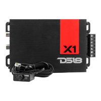
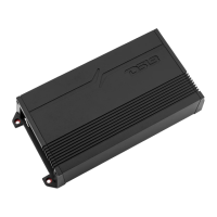
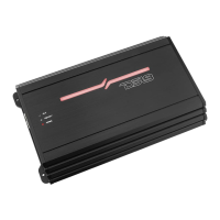
The DS18 CANDY-X series amplifiers are Class D amplifiers designed to power subwoofers (monoblock models like CANDY-X1B and XXL1B) or provide full-range stereo amplification (stereo models like CANDY-X2B, X4B, and X5B). They are built with advanced electronic technology to ensure robust performance and audio fidelity in a car audio environment.
Usage Features:
The amplifiers offer a comprehensive set of controls for tailoring the audio output to specific speaker configurations and listening preferences.
- HIGH INPUT: These terminals allow connection of high-level signals, typically from a factory head unit that lacks RCA outputs.
- LOW INPUT (RCA): These are the primary inputs for connecting low-level signals from a source unit (head unit) or an external electronic crossover. The CANDY-X1B, X4B, and X5B models feature multiple RCA input pairs for their respective channels (e.g., CH1/CH2, CH3/CH4 for the X4B, and 1/2CH, 3/4CH, CH5A for the X5B).
- LOW LEVEL OUTPUT (RCA): The CANDY-X2B and X5B models include a daisy chain output, allowing the low-level signal to be passed to another amplifier, simplifying multi-amplifier setups.
- GAIN Knob: This control adjusts the input sensitivity (volume) of the amplifier, allowing it to match the output level of the source unit. It's crucial for achieving optimal signal-to-noise ratio and preventing distortion.
- SUB GAIN Knob (CANDY-X5B): Specifically for the 5-channel amplifier, this knob adjusts the volume of the subwoofer channel independently.
Crossover and Bass Enhancement Controls:
- LPF (Low Pass Filter) Knob: This knob adjusts the low-pass frequency, allowing only frequencies below the set point to pass through to the speakers. This is essential for subwoofers and for integrating full-range speakers with a subwoofer. The frequency range typically spans from 50Hz to 150Hz.
- HPF (High Pass Filter) Knob: Available on multi-channel and full-range models (CANDY-X2B, X4B, X5B), this knob adjusts the high-pass frequency, allowing only frequencies above the set point to pass. This is used for full-range speakers to prevent them from playing low frequencies they cannot reproduce effectively. The frequency range typically spans from 40Hz to 250Hz.
- X-OVER Switches: These switches provide options for the crossover mode:
- HPF: Activates the high-pass filter.
- FULL: Bypasses all filters, allowing the full frequency range to pass.
- LPF: Activates the low-pass filter.
- Some models (CANDY-X4B, X5B) offer separate X-OVER switches for different channel groups (e.g., CH1/CH2, CH3/CH4, CH5).
- BASS BOOST Knob: This control allows for boosting low frequencies, typically ranging from 0dB to 18dB (CANDY-X1B, XXL1B) or 0dB to 12dB (CANDY-X2B, X4B, X5B).
- BOOST FREQUENCY Knob: This knob adjusts the center frequency at which the bass boost is applied, typically ranging from 40Hz to 100Hz.
Phase Control:
- PHASE CONTROL Switch: This switch adjusts the phase of the output signal, typically between 0° and 180°. This is particularly useful for subwoofers to ensure proper acoustic alignment with other speakers in the vehicle, preventing cancellation or reinforcement issues.
Remote Control:
- REMOTE CONTROLLER OUTLET: This port connects to the included remote controller.
- REMOTE CONTROLLER (Box): This external knob allows for convenient adjustment of the gain (for monoblock models) or subwoofer gain (for 5-channel models) from the driver's seat. It's recommended to set the amplifier's main gain knob to maximum before using the remote for optimal control.
Power and Protection Indicators:
- INDICATOR LIGHT: This LED provides visual feedback on the amplifier's status:
- Blue light: Indicates the amplifier is powered on and operating normally.
- Red light: Indicates the amplifier is in self-protection mode due to an issue (e.g., short circuit, overheating).
Wiring Terminals:
- GND (Ground) Terminal: Connects to the car chassis. The ground cable should be kept as short as possible for optimal performance and safety.
- REM (Remote) Terminal: Connects to the remote turn-on lead from the source unit. This signal (10-15V DC) tells the amplifier when to turn on and off with the head unit.
- +12V Terminal: Connects to the positive terminal of the car battery.
- FUSE: Houses standard automatic fuses. If a fuse needs replacement, it's crucial to use a fuse of the same type and rating.
- SPEAKER Terminals: Connect to the speakers. The manual illustrates various wiring configurations for different speaker impedance loads (e.g., 2-8 Ohm, 1-8 Ohm, 2-4 Ohm, 4-8 Ohm) and bridging modes.
Wiring Configurations:
The manual provides detailed diagrams for various speaker configurations:
- CANDY-X1B / XXL1B:
- 2 Speaker Configuration (monoblock, typically for subwoofers).
- Single Speaker Configuration (monoblock, typically for a single subwoofer).
- CANDY-X2B:
- 2 Channels Stereo Configuration.
- Bridged Mode Configuration (combining two channels to power a single, higher-power speaker).
- CANDY-X4B:
- 4 Channels Stereo Configuration.
- 3 Channels Bridged Mode Configuration (e.g., two channels stereo, one bridged for a subwoofer).
- 2 Channels Bridged Mode Configuration (e.g., two channels bridged for two higher-power speakers).
- CANDY-X5B:
- 5 Channels Stereo Configuration (four full-range channels plus one subwoofer channel).
Maintenance Features:
The manual includes a troubleshooting section to help users diagnose and resolve common issues, which indirectly serves as a guide for basic maintenance and problem identification.
Troubleshooting Guide:
- Amplifier Will Not Power Up: Checks include verifying ground connection, remote DC terminal voltage (at least 10V DC), battery power on the + terminal, fuse integrity, and the status of the protection LED.
- High Hiss or Engine Noise (Alternator Whine) in Speakers: Suggests disconnecting RCA inputs to isolate the source of noise. Emphasizes setting the amplifier input level as insensitive as possible and driving a high signal level from the head unit. Poorly grounded RCA patch cords are identified as a common cause of squeal noise.
- Protection LED Comes On When the Amplifier is Powered Up: Checks include speaker lead shorts, low volume control on the head unit, and resetting the amplifier. Notes that if the LED remains red, the amplifier may be faulty. Also mentions automatic shutdown due to overheating (above 85°C) as a protection mechanism.
- Amplifier Gets Very Hot: Checks include verifying minimum speaker impedance, speaker shorts, and ensuring good airflow around the amplifier. Suggests an external cooling fan might be necessary in some applications.
- Distorted Sound: Checks include matching the level control to the head unit's signal level, proper crossover frequency settings, and speaker lead shorts.
General Warnings and Best Practices:
- Avoid excessively high volume to prevent speaker damage.
- Exercise caution when installing the amplifier near the fuel tank or electrical wires.
- Protect connecting wires and components from damage or short circuits.
- Ensure the power lead from the battery is fused.
- Always turn off the sound system when checking the amplifier.
- Use only the same type of fuse for replacement.
- DS18 reserves the right to make product changes or improvements without prior notice.
The manual emphasizes proper installation and configuration to ensure the longevity and optimal performance of the DS18 CANDY-X amplifiers.