EasyManua.ls Logo

DSC 3G2060 - User Manual

DSC 3G2060
48 pages
Print Icon
To Next Page IconTo Next Page
Loading...
3G2060
HSPA Cellular Alarm Communicator – International
TL2603G
Internet and HSPA Dual-path Alarm Communicator –
International
TL260
Internet Alarm Communicator – International
INSTALLATION MANUAL V3.0
Warning: This manual contains information on limitations regarding product use and func-
tion and information on the limitations as to liability of the manufacturer.

Questions and Answers

  • W
    whitepeterAug 19, 2025
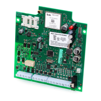
    What to do if my DSC Cell Phone shows no indication?
    • D
      Deanna WrightAug 19, 2025
      If your DSC Cell Phone shows no indication, the cause may be no power. Check the power connections between the panel and the communicator. Also, confirm the PC-LINK cable is properly installed between the communicator and the panel.
  • C
    Cameron VargasAug 21, 2025
    Why is the yellow LED on my DSC 3G2060 solid?
    • T
      tallenAug 21, 2025
      A solid yellow LED on your DSC Cell Phone indicates insufficient signal strength. First, confirm that cellular network service is active in your area. Next, ensure the antenna is securely connected to the radio and that the antenna stub cable is also securely connected. If you're using an external antenna, check that it's securely screwed onto the antenna cable connector and inspect it for any damage or shorts.
  • S
    Stacey LeeAug 23, 2025
    What does it mean when the red and yellow LEDs are flashing together on my DSC 3G2060 Cell Phone?
    • B
      byrdderekAug 23, 2025
      If the red and yellow LEDs are flashing together on your DSC Cell Phone, the unit is still initializing. Wait while the unit gets its programming and establishes a connection to all programmed receivers. This process may take several minutes to complete.
  • S
    sbennettAug 26, 2025
    What does it mean when the yellow LED on my DSC 3G2060 flashes 5 times?
    • H
      helen31Aug 26, 2025
      If the yellow LED on your DSC Cell Phone flashes 5 times, confirm that cellular service is available and active in your area. Check all antenna connections. Ensure average radio signal strength is CSQ 5 or higher. Ensure the SIM card is properly inserted into the SIM card holder and that it has been activated (this could take up to 24 hours after install). If this trouble persists, relocate the panel (and communicator) or install an external antenna extension kit.
  • M
    Michelle GrantAug 27, 2025
    What does it mean when the yellow LED on my DSC 3G2060 flashes 6 times?
    • R
      robert19Aug 28, 2025
      If the yellow LED on your DSC Cell Phone flashes 6 times, check with your ISP to confirm Internet service is active in your area. Ensure your Ethernet cable is securely inserted into the RJ45 jack of the communicator and the Hub/Router/Switch. Check the link light on the Hub/Router/Switch is ON; if it's OFF, try restarting the Hub/Router/Switch. If DHCP is used, ensure that the unit has an assigned IP address from the server. Verify a valid IP address is programmed. If not, contact the Network administrator. If the problem persists, replace the Ethernet cable and RJ45 connector.
  • F
    frederick62Aug 30, 2025
    What does it mean when the yellow LED on my DSC Cell Phone flashes 7 times?
    • S
      Sheila MooreAug 30, 2025
      If the yellow LED on your DSC Cell Phone flashes 7 times, ensure that the Ethernet path has internet connectivity. If you are using a static IP address make sure the gateway and subnet mask are entered correctly. If the network has a firewall, ensure the network has the programmed outgoing ports open (Default UDP Port 3060 and Port 3065). Ensure that all the receivers are programmed for DHCP or have the proper IP address and port number. Ensure the cellular receiver APNs have been programmed with the Access Point Name provided by your cellular provider.
  • J
    Jacob BrownSep 1, 2025
    What does it mean when the yellow LED on my DSC 3G2060 flashes 8 times?
    • S
      Shawn PerkinsSep 1, 2025
      If the yellow LED on your DSC Cell Phone flashes 8 times, this indicates a trouble when supervision is enabled and the unit is not able to successfully communicate with the receiver. If this trouble persists, contact your central station.
  • L
    Laura BrooksSep 4, 2025
    What does it mean when the yellow LED on my DSC Cell Phone flashes 9 times?
    • M
      Michael LynchSep 4, 2025
      If the yellow LED on your DSC Cell Phone flashes 9 times, the unit has exhausted all communications attempts to all programmed receiver for events generated by the Communicator. Restart the system, if trouble persists, contact your dealer.
  • M
    mcneilbarrySep 6, 2025
    Why is the trouble LED on my DSC 3G2060 Cell Phone flashing twice?
    • E
      Eric PetersonSep 6, 2025
      If the trouble LED on your DSC Cell Phone is flashing twice, it indicates a panel supervision trouble. Check that Section [382] Toggle Option [5] is ON (cellular/Ethernet Module Enabled). Also, ensure the PC-LINK cable between the panel and communicator is connected properly (not reversed) and is securely in place.
  • S
    snelsonSep 8, 2025
    What does it mean when the yellow LED on my DSC Cell Phone flashes 4 times?
    • G
      gonzalezmichealSep 8, 2025
      If the yellow LED on your DSC Cell Phone flashes 4 times, the SIM card has an incorrect PIN programmed or has a PIN that the module does not recognize. Replace the SIM card.

Summary

Installer Safety Warnings

Critical Safety Precautions

Essential warnings for installers regarding product operation, limitations, and potential hazards.

General Information and Model Overview

Manual Usage and Safety Guidelines

Guidance on manual use, general safety, and important notes for installers.

Communicator Model Descriptions

Details on different communicator models (3G2060, TL2603G, TL260) and their features.

Panel Mounting Compatibility

Information on which panels are compatible with the listed communicators.

Communicator Features and Specifications

Product Features List

Key features of the 3G Alarm Communicator, including encryption and connectivity options.

Cellular Frequency Bands by Market

Technical specifications detailing cellular frequency bands for various global markets.

Pre-Installation Configuration

Remote Programming Setup via DLS 5

Steps for configuring remote programming using DLS 5 software via SMS.

Communicator Installation Configuration

Ethernet Cable Installation Guide

Guidelines for installing the CAT 5 Ethernet cable for TL2603G/TL260 models.

SIM Card Insertion and Removal Procedure

Procedure for inserting and removing the SIM card from the communicator module.

Installing Cellular;Ethernet Communicator in Panel

Mounting Bracket Assembly

Instructions for assembling the mounting bracket for the communicator.

Communicator to Panel Connection

Steps for connecting the communicator to the panel via PC-LINK and antenna.

Communicator Wiring and Connections

Module Power and Ground Connections

Wiring instructions for powering the communicator module from the panel.

Optional External Bell;Siren Wiring

Wiring details for connecting an optional external bell or siren.

Communicator Connectivity and Power-Up

Keybus and Network Cable Installation

Connecting the keybus and network cables to the communicator and panel.

Initial Power-Up and LED Status Observation

Procedure for initial power-up and observing communicator status LEDs.

Communicator Placement and Initial Programming

Cellular Placement Test Procedure

Steps to ensure optimal cellular signal strength by testing antenna location.

Keypad Data Display and Programming Access

Explanation of keypad display formats and access methods for programming.

Initial Panel and Communicator Programming

Panel Programming Section Details

Required panel programming sections and options for communicator integration.

Account and Central Station Setup

Programming the account number, central station phone numbers, and communication format.

Communicator Status LEDs

Yellow Trouble LED Indications

Explanation of the yellow trouble LED and its flash codes for diagnosing issues.

Detailed LED Status and Network Indicators

Trouble Codes and Descriptions

Detailed descriptions of various trouble conditions indicated by LED flashes.

Red Network Connection Status LED

Meaning of the red network connection status LED for Ethernet/TL260.

Communicator Reset and Firmware Management

Factory Defaults Reset Procedure

Steps to reset the communicator programming to factory default settings.

Firmware Update Process

Information on how to update the device firmware via cellular or Ethernet.

Communicator Troubleshooting Guide

Trouble LED Indications and Solutions

Table detailing trouble indications, possible causes, and solutions based on LED status.

Ethernet;Cellular Programming Options

System Options Configuration

Configuration settings for IP addresses, subnet masks, gateways, and supervision intervals.

System Toggle and Network Options

System Toggle Options 1 and 2

Configuration of receiver supervision, primary path, and enabling/disabling receivers.

Network and Programming Options

DNS Server and DLS Port Configuration

Settings for DNS server IP addresses and the DLS incoming port for remote access.

Communication Protocols and Reporting Codes

DLS Outgoing Port and Account Code Setup

Configuration for DLS outgoing port and account codes for event transmission.

Communications Format and Reporting Codes

Setting the communications format (CID/SIA) and defining reporting codes for events.

System Test Transmission Configuration

Ethernet Test Transmission Settings

Configuring the time and cycle for Ethernet test transmissions.

Ethernet Receiver 1 Configuration

Account, DNIS, and Address Settings

Setting the account code, DNIS, and IP address for Ethernet Receiver 1.

Remote and Local Port Settings

Configuring the remote and local ports for Ethernet Receiver 1.

Ethernet Receiver 2 Configuration

Account, DNIS, and Address Settings

Setting the account code, DNIS, and IP address for Ethernet Receiver 2.

Remote and Local Port Settings

Configuring the remote and local ports for Ethernet Receiver 2.

Ethernet Transmission Options

Ethernet Test Transmission Time and Cycle

Configuring the time and cycle for Ethernet test transmissions.

Cellular Receiver 1 Configuration

Account, DNIS, and Address Settings

Setting the account code, DNIS, and IP address for Cellular Receiver 1.

Port and APN Settings

Configuring the port and APN for Cellular Receiver 1 connection.

Cellular Network and Receiver 2 Configuration

Cellular Receiver 1 APN and Domain Name

Configuring the APN and domain name for Cellular Receiver 1 connection.

Cellular Receiver 2 Configuration Details

Settings for Cellular Receiver 2 account, DNIS, address, port, APN, and domain.

Cellular Options and Test Transmission

Cellular Network Access and Credentials

Configuration for cellular public APN, login credentials.

Cellular Test Transmission and Trouble Delay

Configuring cellular test transmission cycles and trouble delay settings.

System Information (Read Only)

View Network and Version Information

Displaying language version, DNS, Ethernet, and Cellular IP addresses.

View Firmware, SIM, and IMEI Details

Displaying firmware version, SIM card details, IMEI, and MAC address.

System Resets and Firmware Diagnostics

System Reset Options

Procedures for resetting the communicator to software defaults or performing a hard reset.

Firmware Update Diagnostic Codes

Interpreting diagnostic codes related to firmware update processes.

Communicator Status and Radio Signal Strength

Communicator Status Code Interpretation

Understanding the 6-digit hexadecimal status code and its components.

Radio Signal Strength Indicators and Actions

Interpreting signal strength indicators and troubleshooting weak signals.

Network and Radio Status Indicators

Network Indicator Value Meanings

Interpreting the network indicator values (OFF, ON, Flashing).

Trouble Code Indicators and Causes

Mapping trouble indicators to specific causes and troubleshooting steps.

Radio Initialization Status Breakdown

Understanding the 8-digit status code for radio communication initialization.

Radio Initialization Status Details

Radio Initialization Status Bit Meanings

Detailed breakdown of each bit's meaning in the radio initialization status code.

Ethernet;Cellular Programming Worksheets

System Options and Network Configuration Worksheets

Worksheets for system options, network settings, and DNS server configuration.

Receiver Configuration Worksheets

Ethernet Receiver Configuration Worksheets

Worksheet for configuring Ethernet receivers 1 and 2, and Ethernet test transmission.

Cellular Receiver 1 Configuration Worksheets

Worksheet for configuring Cellular Receiver 1 settings.

Cellular and Event Notification Worksheets

Cellular Receiver 2 and Options Worksheets

Worksheet for configuring Cellular Receiver 2 and general cellular options.

Event Notification and SMS Options Worksheets

Worksheet for configuring event notifications and SMS telephone numbers.

SMS Notification and Label Programming Worksheets

SMS Telephone Number Toggle Options

Worksheet for configuring toggle options for SMS notifications per telephone number.

Area and System Label Programming

Worksheet for programming labels for areas, systems, and partitions.

User and Zone Label Programming Worksheets

User Label Programming Worksheets

Worksheet for programming custom labels for up to 40 users.

Zone Label Programming Worksheets

Worksheet for programming custom labels for up to 51 zones.

External Event Label Programming Worksheets

External Event Label Configuration Worksheets

Worksheet for programming custom labels for various external alarm and trouble events.

Internal Event and SMS Interactive Worksheets

Internal Event Label Programming Worksheets

Worksheet for programming custom labels for internal events.

SMS Interactive Functions Worksheets

Worksheet for configuring SMS interactive functions and responses.

SMS Response and System Information Worksheets

SMS Interactive Response Labels Worksheets

Worksheet for programming labels for SMS interactive responses.

System Information Read Only Worksheets

Worksheet section for viewing system information like IP addresses and firmware versions.

Diagnostic Testing and System Info Worksheets

Diagnostic Test Transmission Worksheets

Worksheet for configuring diagnostic test transmissions to receivers.

System Reset Defaults Worksheet

Software Default Reset Configuration Worksheets

Worksheet for configuring system reset defaults, including software defaults.

End User License Agreement (EULA)

License Grant and Restrictions

Legal terms regarding software installation, use, backup, and limitations on reverse engineering.

Limited Warranty Information

Warranty Terms and Conditions

Details of the limited warranty, including coverage, exclusions, and repair procedures.

EN50131-1 Installation Compliance

Required Programming for EN50131-1

Specific programming settings required for EN50131-1 certified installations.

EN50131 Compliant Installation Details

Information on product conformance to EN50131-1 standards for radiated emissions and security levels.

DSC 3G2060 Specifications

General IconGeneral
NetworkGSM 900 / 1800 / 1900
Memory1MB
Stand-byUp to 200 h
Talk timeUp to 3 h
ColorsBlack

Related product manuals