Do you have a question about the DSC GS3055-IG and is the answer not in the manual?
Details the capabilities and functionalities of the GS3055 device, covering landline simulation, GSM network usage, and SMS/Contact ID features.
Provides detailed technical parameters including input voltage, current ratings, operating frequency, dimensions, and weight.
Offers a general overview of the device's purpose as a backup wireless communicator for alarm systems.
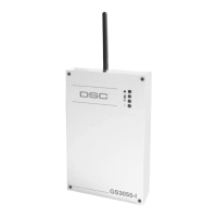
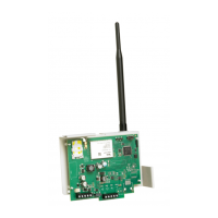
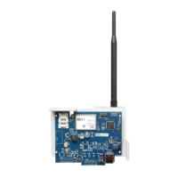
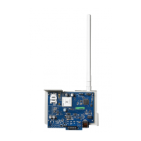
Lists and identifies the physical components of the GS3055 device, referencing Figure 1 for visual aid.
Outlines the step-by-step procedure for physically installing the GS3055 device, including placement and wiring precautions.
Details the wiring connections for various terminals, including power, telephone lines, outputs, and tamper inputs.
Explains the meaning of the device's status LEDs (Red, Yellow, Green) and their blinking patterns for different operational states.
Describes how the device simulates a landline connection, providing a backup for PSTN line failures.
Details the operational sequence when an alarm is triggered and the device initiates communication.
Explains the device's capability to send SMS messages for various alarm events and system status updates.
Describes how the device transmits alarm signals using the Contact ID protocol to central stations.
Defines the priority for handling communications, such as Simulated Land Line, SMS, or Contact ID events.
Explains how to configure and control the device's four programmable outputs for automatic or remote activation.
Details how outputs can be automatically triggered by specific system events like line trouble or GSM module issues.
Describes how outputs can be controlled remotely via SMS text messages or telephone calls.
Explains how bistable outputs can be toggled ON/OFF using SMS commands or remote calls for appliance control.
Details how monostable outputs activate for a set duration, controlled by SMS or remote calls.
Provides instructions for programming the GS3055 using the dedicated software application via an RS232 connection.
Covers the configuration of the device's phonebook for SMS and dialer functions, including number management and remote control.
Details the fields for entering and managing telephone numbers for SMS and dialer operations.
Explains how to set a prefix that will be added to all dialed numbers via the GSM interface.
Describes the setting to remove digits from numbers, often required when connecting through a switchboard.
Outlines the configuration of SMS dialer functions, message settings, and special functions for input lines.
Describes the main interface elements within the SMS Dialer configuration page.
Allows selection of the operating priority for the device, such as Interface or SMS Dialer/Contact ID Communicator.
Explains how to set up SMS notifications for the end-user's credit balance with GSM network providers.
Covers the configuration of periodic status messages, including date, time, and interval settings.
Provides interface for setting up and controlling the device's outputs, including event triggers and feedback.
Details the configuration options for outputs, such as polarity, event assignments, and feedback signals.
Describes setting an access code for controlling outputs via telephone.
Allows configuration of Contact ID reporting, including telephone numbers and event code mapping.
Specifies the telephone numbers the device will attempt to call for Contact ID reporting.
Explains how to define Customer Codes and map events to specific Contact ID codes for reporting.
Provides default Contact ID event codes for common alarm system events, referencing Sur-Gard System III/II.
Option to enable sending Contact ID events exclusively via the GPRS network.
Configuration settings for periodic Contact ID reports, including date, time, and interval.
Outlines all GPRS configuration options, including APN, IP addresses, user credentials, and dial-in numbers.
Field to enter the Access Point Name provided by the GPRS service provider for network connectivity.
Specifies the primary and back-up IP addresses and ports for the central station receiver.
Allows entry of user name and password required by some providers for GPRS authentication.
Configures specific numbers to trigger GPRS communication when dialed by the panel.
Setting for Dialled Number Identification Service number, used for landline communication identification.
Entry for the account code required for communication with Sur-Gard receivers.
Enables viewing of dialled, received, and missed calls made by the device.
Button to load and display call log history on the Calls Page.
Section to view incoming calls received by the device.
Section to view incoming calls that were not answered.
Section to view outgoing calls made by the device.
Provides a real-time interface for monitoring device functions, GSM status, battery, and signal reception.
Displays detailed GSM module data, network provider, battery charge, and signal strength.
Shows the status of the four input lines, indicating whether they are balanced or unbalanced.
Displays the status of the four output channels, indicating whether they are in standby or activated.
Logs and displays events as they occur, typically indicated by a RED LED status.
Shows the scheduled date and time for the next periodic SMS message transmission.
Shows the scheduled date and time for the next periodic Contact ID report.
Allows interruption of ongoing calls and stopping the outgoing call queue.
A section providing general user guidance and further references for device operation.
Information regarding the device's capability to make calls over the GSM network.
Points to other sections in the manual for additional details on specific features.
Details the FCC regulations and compliance for radio frequency energy emission and interference.
Provides critical safety warnings regarding RF exposure and minimum separation distances for the antenna.
| Network Technology | GSM |
|---|---|
| EDGE | No |
| SIM | Mini-SIM |
| Loudspeaker | Yes |
| Games | Yes |
| Alert types | Vibration |
| Radio | FM radio |
| Messaging | SMS |
| Battery | Li-Ion |
| Colors | Black |