EasyManua.ls Logo

DSC TL260GS - User Manual

DSC TL260GS
33 pages
Print Icon
To Next Page IconTo Next Page
Loading...
TL260GS / TL265GS
Internet and GSM / GPRS Dual-Path Alarm Communicator
GS2060 / GS2065
GSM / GPRS Wireless Alarm Communicator
Software Version 1.0
Installation Manual

Questions and Answers

  • D
    David DayAug 17, 2025
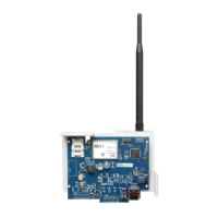
    What to do if the Trouble LED is flashing 5 times on my DSC TL260GS Cell Phone?
    • M
      Miguel RamirezAug 18, 2025
      If the Trouble LED on your DSC Cell Phone is flashing 5 times, it indicates a GSM issue. Make sure the SIM card is activated and properly inserted into the SIM card holder. Also, check the signal strength indicators; if the signal is weak, relocate the communicator module or use an external antenna extension kit.
  • K
    Kimberly CopelandAug 20, 2025
    How to fix a DSC Cell Phone with no indicators?
    • N
      natalie94Aug 20, 2025
      If all indicators are off on your DSC Cell Phone, it could be due to several reasons: * **No Power:** Check the power connections to both the control panel and the communicator module. * **Power Save Mode (TL265GS/GS2065 only):** The control panel might be in power save mode. Verify the AC source to the control panel. * **Keypad Blanking Mode (TL265GS/ GS2065 only):** The control panel might be in keypad blanking. Press a key on a keypad to remove blanking momentarily.
  • P
    phillipsannAug 22, 2025
    What to do if the Trouble LED is flashing 6 times on my DSC TL260GS Cell Phone?
    • M
      Michele VegaAug 23, 2025
      If the Trouble LED on your DSC Cell Phone is flashing 6 times, it signifies an Ethernet issue. First, ensure your Ethernet cable is securely inserted into the Ethernet jack. Check that the link light on the HUB is ON; if not, try replacing the Ethernet cable. If DHCP is used, verify that the unit is successfully obtaining an IP address from the server by checking section [851] [992]. If a valid IP address is not present, contact the Network administrator.
  • S
    Steven LewisAug 25, 2025
    What causes the Trouble LED to be on solid on my DSC Cell Phone?
    • B
      Bruce MooreAug 26, 2025
      A solid Trouble LED on your DSC Cell Phone usually indicates no signal strength. Ensure the antenna is securely connected to the radio and check the cable connection to the radio. If a WIP antenna is used, ensure it is securely screwed onto the antenna cable connector.
  • J
    Joseph ReynoldsAug 27, 2025
    Why is the Trouble LED flashing 7 times on my DSC TL260GS Cell Phone, and how can I fix it?
    • Y
      youngseanAug 27, 2025
      If the Trouble LED is flashing 7 times on your DSC Cell Phone, it means the receiver is not available. Here’s what you should check: * Ensure the Ethernet path has internet connectivity. * If using a static IP address, verify the gateway is correct. * If a firewall is present, ensure the programmed outgoing ports are open (Default UDP Port 3060 and Port 3065). * Ensure all receivers are programmed with the proper IP and port. * Ensure all receivers are programmed with a valid account number. * Ensure the System Account code has been programmed with a valid account code.
  • S
    stephanierichardsonAug 30, 2025
    Why are the red and yellow indicators flashing simultaneously on my DSC TL260GS Cell Phone?
    • L
      Lisa McdonaldAug 30, 2025
      If the red and yellow indicators are flashing at the same time on your DSC Cell Phone, it means the unit is in the initialization sequence. Please wait while the unit gets its programming from Connect 24 and establishes a connection to all programmed receivers. This process may take several minutes.
  • M
    Matthew SmithSep 1, 2025
    What does it mean when the Trouble LED flashes twice on my DSC TL260GS Cell Phone?
    • M
      Marcus BrownSep 2, 2025
      If the Trouble LED flashes twice on your DSC Cell Phone, it indicates a panel supervision trouble. Check section [382] option 5 on the control panel and ensure that it is set to ON. Also, ensure the PC-Link cable between the control panel and module is securely in place and not reversed.
  • J
    Jonathan BellSep 4, 2025
    What does it mean when the Trouble LED flashes 8 times on my DSC Cell Phone?
    • A
      Andrew WeaverSep 4, 2025
      When the Trouble LED flashes 8 times on your DSC Cell Phone, it indicates a receiver supervision trouble. This happens when supervision is enabled, and the unit cannot communicate with the receiver. If this issue continues, contact your central station.
  • K
    Kayla HerreraSep 6, 2025
    What does it mean if the Trouble LED flashes 4 times on my DSC Cell Phone?
    • D
      drhodesSep 6, 2025
      If the Trouble LED on your DSC Cell Phone flashes 4 times, it indicates a lockout trouble. This means the SIM card requires a PIN number that the module does not recognize. Try using a different SIM card.
  • J
    Jeffrey ScottSep 9, 2025
    What does it mean when the Trouble LED flashes 10 times on my DSC TL260GS?
    • B
      Beth ChenSep 9, 2025
      If the Trouble LED flashes 10 times on your DSC Cell Phone, it indicates a Connect 24 configuration failure. Ensure a profile has been programmed in Connect 24 for the module. You can confirm your programming by calling the Connect 24 VRU, or by logging into the Connect 24 VRU web site.

Summary

Limited Warranty

Warranty Procedure

Procedure for obtaining warranty service and returning products for repair.

Conditions to Void Warranty

List of conditions that will void the product's warranty.

Items Not Covered by Warranty

Specifies items and situations not covered by the warranty.

Disclaimer of Warranties

Out of Warranty Repairs

Details procedures and costs for repairing products outside the warranty period.

WARNING

Note to Installers

Important information for installers to convey to system users regarding system limitations.

System Failures

Discusses circumstances where the system may fail to provide protection.

Criminal Knowledge

Addresses the possibility of criminals developing techniques to bypass system features.

Access by Intruders

Explains how intruders might circumvent the security system's detection.

WARNING

Power Failure

Explains the impact of power interruptions on system operation and potential damage.

Failure of Replaceable Batteries

Discusses battery life, factors affecting it, and low battery monitoring.

Compromise of Radio Frequency Devices

Describes potential interference with wireless signals.

Smoke Detectors

Explains limitations and reasons why smoke detectors might not alert occupants.

Warning

FCC Compliance

Compliance statement and guidelines for using the equipment to avoid interference.

Industry Canada Statement

Compliance statement for digital apparatus according to Canadian standards.

IMPORTANT - READ CAREFULLY

Software Product License Terms

Outlines the terms and conditions governing the use of the software product.

Grant of License Rights

Details the rights granted to the user for software installation, storage, and backup copies.

Software Rights and Limitations

Specifies limitations on reverse engineering, decompilation, and modifications.

Limited Warranty Details

No Warranty Clause

States that the software is provided 'as is' without express or implied warranties.

Operating Environment Changes

DSC is not responsible for issues arising from hardware changes or interactions.

Limitation of Liability and Risk

Limits DSC's liability and states that warranty reflects risk allocation.

Disclaimer of All Other Warranties

Reaffirms that this warranty is exclusive and supersedes all others.

Exclusive Remedy and Warranty Limits

Exclusive Remedy and Damage Limitation

Defines the exclusive remedy and limits liability for damages.

Introduction to Communicator

Communicator Models Overview

Lists and briefly describes the available communicator models.

Key Communicator Features

Highlights the main functionalities and capabilities of the communicator.

Technical Specifications

Communicator Ratings

Compatibility Information

Installing the GSM;Ethernet Communicator

CONNECT 24 Activation Process

Steps and contact information for activating the communicator with CONNECT 24.

Communicator Installation Guides

Installation with PC1616;1832;1864 Panels

Step-by-step guide for installing the communicator with specific control panels.

Communicator Wiring Diagrams

TL260 GS;GS2060 Wiring and Antenna Kits

Wiring diagram for TL260GS/GS2060 and optional GSM antenna kits.

Installation with PC9155 Control Panel

Instructions for installing the communicator with the PC9155 control panel.

TL265 GS;GS2065 Wiring and Antenna Kits

Optional Antenna Kits for PC9155

Options for external GSM radio antenna kits for the PC9155 enclosure.

PC1616; PC1832; PC1864 Programming Options

Programming Options 301, 302, 303

Details programming options for telephone numbers and communication paths.

Programming Option 350

Specifies the setting for communication format (SIA FSK).

Programming Option 382

Explains the setting for T-Link Interface Enable.

PC9155 Programming Options

PC9155 Communication Path Options

Configuration options for communication paths on the PC9155 panel.

PC9155 Communication Format Option

Specifies the setting for communication format (SIA).

STATUS LEDs Overview

Trouble Status LED

Explains the function and flash codes of the Trouble Status LED.

Panel Supervision Trouble

Describes the 'Panel Supervision Trouble' condition indicated by the LED.

Detailed Trouble Status Indicators

Trouble Status LED Explanations

Explains specific trouble conditions like Lockout, GSM, Ethernet, and Receiver issues.

Communication and Configuration Troubles

Details troubles related to FTC, Connect24, Remote Programming, and Firmware Updates.

Network and Signal Strength LEDs

Network Connection Status LED

Explains the function and activation of the Network Connection Status LED.

Radio Signal Strength LEDs

Details how signal strength LEDs indicate radio signal levels.

Adding an Antenna Extension

Steps for installing an antenna extension kit to improve signal strength.

Hardware Default Jumper Function

Instructions on how to use the hardware default jumper to reset options.

Communicator Troubles on 9155 Panel

9155 Panel Trouble Table

Lists communicator trouble conditions and user actions for the 9155 panel.

Loss of Time and Date Trouble

Describes the 'Loss of Time and Date' trouble and how to resolve it.

Communicator Troubles on 1616;1832;1864 Panels

Firmware Upgrade Default Settings

UL Firmware Update Procedures

UL Remote Flash Update Operation

Process and requirements for UL remote flash updates.

Communicator Options Overview

System Options Configuration

Configuration settings for Ethernet IP, supervision, and system toggles.

Programming and Receiver Options

Settings for installer code, DLS ports, and Ethernet/GPRS receiver configurations.

GPRS Network and System Information

Settings for GPRS APN, login credentials, and viewing system information.

Ethernet Interface Configuration

Ethernet IP, Subnet Mask, and Gateway

Detailed settings for Ethernet IP Address, Subnet Mask, and Gateway IP Address.

Receiver Supervision and System Toggles

Configuration for receiver supervision intervals and system-wide toggle options.

Installer and DLS Configuration

Installer Code and DLS Port Settings

Configuration of installer code and DLS connection ports for the communicator.

Ethernet Receiver 1 Setup

Settings for account code, DNIS, and IP address of the first Ethernet receiver.

Ethernet Receiver Port Configuration

Ethernet Receiver 1 Ports

Configuration of local and remote ports for Ethernet Receiver 1.

Ethernet Receiver 2 Setup

Settings for account code, DNIS, and IP address of the second Ethernet receiver.

Ethernet Receiver 2 Ports

Ethernet Receiver 2 Ports Configuration

Configuration of local and remote ports for Ethernet Receiver 2.

GPRS Receiver 1 Setup

Settings for account code, DNIS, and IP address of GPRS Receiver 1.

GPRS Receiver Port and APN Settings

GPRS Receiver 1 Ports and APN

Configuration of port and APN for GPRS Receiver 1.

GPRS Receiver 2 Setup

Settings for account code, DNIS, and IP address of GPRS Receiver 2.

GPRS Login and System Info

GPRS Receiver 2 Ports and APN

Configuration of port and APN for GPRS Receiver 2.

GPRS Login and System Information Access

Settings for GPRS login credentials and viewing system information.

System Information Confirmation

Confirm Firmware, IP, SIM, Phone, IMEI, MAC

Options to confirm firmware, IP, SIM, phone, IMEI, and MAC details.

Software Default and Unit Reset

Option to reset programming to factory defaults.

Troubleshooting Guide

DSC TL260GS Specifications

General IconGeneral
SIMDual SIM
Display2.4"
Resolution240 x 320
Rear CameraVGA
Front CameraNo

Related product manuals