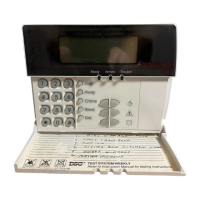
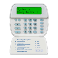
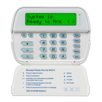
The LCD5511 keypad presents system status using an LCD display along with symbols and
numbers. The keypad can be used on security systems with up to 64 zones. The LCD5511
is compatible with the following DSC security systems:
• PC580/PC585 •PC5008
• PC1555/PC1565 •PC50XX
Specifications
• Voltage rating: 12Vdc nominal
• Connects to control panel via 4-wire Keybus
• One keypad zone input/PGM output
• Current draw: 22mA (standby) / 85mA (maximum)
• Optional tamper version
• Four programmable function keys
• Ready (green) and Armed (red) status lights
• Low temperature sensor
Installation
Unpacking
The LCD5511 package includes the following parts:
• One LCD5511 keypad •one tamper switch
• Four mounting screws •surface tape
• one end-of-line resistor •one Installation Manual
• three keypad inner door labels
Mounting
You should mount the keypad where it is accessible to designated points of entry and exit.
Once you have selected a dry and secure location, perform the following steps to mount
the keypad.
1. Remove the keypad backplate by loosening the screw (optional) located at the base of
the unit.
2. Secure the keypad backplate to the wall in the desired location. Use the screws provided.
3. To use the keypad tamper, insert the tamper switch supplied into the opening located in
the centre of the backplate.
4. For tamper use, try to ensure the backplate is mounted on a smooth, flat surface. If
mounting on a rough surface, fasten the enclosed surface tape to the wall to even out the
surface area where the tamper will be positioned.
5. Before attaching the keypad to its backplate, complete the keypad wiring as described in
the next section.
Wiring
1. Before wiring the unit, ensure that all power (AC transformer and battery) is disconnected
from the control panel.
2. Connect the four Keybus wires from the control panel (red, black, yellow and green) to
the keypad terminals (R B Y G). Consult the diagram below:
3. If programmed as an input, you can connect a device
- such as a door contact - to the ‘Z/P’ terminal of the
LCD5511. This eliminates the need to run wires back
to the control panel for the device. To connect the
zone, run one wire from the device to the ‘Z/P’ termi-
nal and the other wire from the device to the B (black)
terminal. For powered devices, run the red wire to the
R (positive) terminal and the black wire to the B (neg-
ative) terminal. When using end of line supervision, connect the zone according to one of
the configurations outlined in your system’s Installation Manual.
4. If the ‘Z/P’ terminal is programmed as an output, the output follows the PGM pro-
grammed in Section [000][8]. A small relay, buzzer or other DC operated device may be
connected between the positive supply voltage and the ‘Z/P’ terminal (maximum load is
50mA).
Applying Power
Once all wiring is complete, apply power to the control panel:
1. Connect the battery leads to the battery.
2. Connect the AC transformer.
For more information on control panel power specifications, see the control panel Installa-
tion Manual.
NOTE: Do not connect the power until all wiring is complete.
Enrolling the Keypad
Once all wiring is complete, you will need to enter a 2-digit number that tells the system
the partition and slot assignment of the keypad.
If your system has partitions, you will need to also assign the keypad to a partition (1st
digit).
The slot assignment (2nd digit) tells the panel which keypad slots are occupied. The panel
can then generate a fault when a keypad supervisory signal is not present. There are eight
available slots for keypads. LCD5511 keypads are always assigned to slot 1 by default.
You will need to assign each keypad to its own slot (1 to 8).
Enter the following at each keypad installed on the system:
1. Enter Installer Programming by pressing [*][8][Installer’s Code]
2. Press [000] for Keypad Programming
3. Press [0] for Partition and Slot Assignment
4. Enter a two digit number to specify the partition and slot assignment.
NOTE: If your system does not have partitions, enter [1] for the first digit.
1st digit: Enter 0 to 8 for partition assignment (0 = Global Keypad).
2nd digit: Enter 1 to 8 for slot assignment.
5. Press the [#] key twice to exit programming.
6. After assigning all keypads, perform a supervisory reset by entering [*][8][Installer’s
Code][902]. The panel will now supervise all assigned keypads and enrolled modules on
the system.
Programming the Keypad
There are several programming options available for the LCD5511 keypad. These are
described below. Record all your programming choices in the programming worksheets
included in this manual.
Programming the LCD5511 is similar to programming the rest of the system. When you
are in the LCD5511 programming sections, the keypad will display which options are
turned on along the top of the display. To turn an option on or off, press the number corre-
sponding to the option on the number pad. The numbers of the options that are currently
turned ON will be displayed.
For example, if options 1 and 2 are on, the display will look like:
For information on programming the rest of your security
system, please refer to your system’s Installation Manual.
Function Key Options
The function keys are programed in sections [000][1-4]. By default, the 4 function keys
on the keypad are programmed as Stay Arm (03), Away Arm (04), Chime (06), Aux (11).
You can change the function of each key on every keypad. Please see your system’s Instal-
lation Manual for instructions on programming the keys, and a complete list of all the
function key options available for your system.
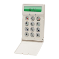
Clock Options
The LCD5511 will display the current time after 4 seconds of no key presses. To set the
correct time and date for the system, please refer to your system’s Instruction Manual. You
can change how the keypad displays the time with the following options. To change the
clock options:
1. Enter [*][8][Installer’s code]
2. Enter [000] to go to keypad programming
3. Enter section [6] to go to clock options.
4. To turn any of the options on or off, press [1], [2], or [3]:
NOTE: If the Time does not display on keypad option is selected, make sure that the
Keypad displays time when zones are open option is also selected.
[1]ON = Time displays on keypad
OFF = Time does not display on keypad
[2]ON = Clock display is in 12-hour format (e.g. 08:00).
OFF = Clock display is in 24-hour format (e.g. 20:00)
[3]ON = Keypad does not display time when zones are open
OFF = Keypad displays time when zones are open
5. When you are finished programming the clock options, press [#] to exit.
Alarms Displayed While Armed Option
You can disable the display of alarms on the keypad when the system is armed. The dis-
play of alarms is enabled by default. To disable the display of alarms when the system is
armed, turn off section [6], option [5]:
1. Enter [*][8][Installer’s code]
2. Enter [000] to go to keypad programming
3. To turn the display of alarms on or off, enter section [6].
4. Turn option [5] on or off:
[5]ON = Alarms not displayed while system is armed
OFF = Alarms are always displayed while system is armed
5. When you are finished, press [#] to exit.
Emergency Key Options (Fire, Auxiliary, Panic)
You can enable or disable the Fire, Auxiliary and Panic keys at each keypad. These keys
are enabled by default. Please see your system’s Installation Manual for more information
on these keys and their options. To turn any of the emergency keys on or off on the key-
pad:
1. Enter [*][8][Installer’s code]
2. Enter [000] to go to keypad programming
3. Enter section [7].
4. To turn the emergency key options on or off, press [1], [2], or [3]:
[1]ON = Fire key enabled
OFF = Fire key disabled
[2]ON = Auxiliary key enabled
OFF =Auxiliary key disabled
[3]ON = Panic key enabled
OFF = Panic key disabled
5. When complete, press [#] to exit.
Door Chime Options
You can program the LCD5511 keypad to sound a tone when any zone is opened or
closed. There are two parts to the LCD5511 door chime programming:
• Program if the LCD5511 will chime when zones are opened and/or closed.
• Program the type of sound the LCD5511 will make when an individual zone is opened or
closed.
For the door chime feature to work, you will also need to turn on the Door Chime attribute
for each zone that will trigger the chime. This programming is done in the control panel
software. Refer to your control panel’s Installation Manual for more information.
Door Chime on Zone Openings/Closings
You can program each LCD5511 keypad to sound a door chime when zones are opened
and/or when they are closed. By default, LCD5511 keypads are programmed to sound
door chimes on both zone openings and closings.
To change the door chime opening/closing settings, at each LCD5511 keypad:
1. Enter [*][8][Installer’s Code]
2. Enter [000] to go to keypad programming
3. Enter section [6].
4. To turn the options on or off, press [6] or [7]:
[6]ON = Door Chime Enabled for Zone Openings
OFF =Door Chime Disabled for Zone Openings
[7]ON = Door Chime Enabled for Zone Closings
OFF =Door Chime Disabled for Zone Closings
5. When you are finished, press [#] to exit.
Door Chime Sounds
You can program the LCD5511 keypad to make different door chime sounds for individual
zones, or groups of zones. Each LCD5511 keypad can make any of four door chime sounds
for each zone that triggers the door chime:
• 4 quick beeps (default sound) •‘Ding – Dong’ tone
• ‘Bing – Bing’ tone •‘Alarm’ tone
NOTE: For a zone to be able to trigger the door chime sound, the Door Chime zone
attribute must also be enabled in the control panel programming. Please see your
control panel Installation Manual.
To change the door chime sounds:
1. Enter [*][8][Installer’s code].
2. Enter [*] to go to door chime sound programming.
3. Enter a 2-digit number for the zone you want to program [01] - [64].
4. Turn one of the following options on by pressing [1], [2], [3], or [4]:
[1]4 quick beeps (default sound)
[2] ‘Bing – Bing’ tone
[3] ‘Ding – Dong’ tone
[4]‘Alarm’ tone
NOTE: Make sure that only one of the above options is turned on. If more than one
is on, the keypad will sound the first option that is enabled. If none of the options
are selected, the keypad will not make any sound when the zone is opened or
closed.
5. To program the door chime sound for another zone, repeat steps 3 and 4.
6. When you are finished programming the door chime sounds, press [#] to exit.
Zone Input/PGM Output Option
The LCD5511 ‘Z/P’ terminal can be programmed to support one zone input (default) or
one PGM output. To change this option:
1. Enter [*][8] [Installer Code].
2. Enter [000] to go to keypad programming.
3. Enter section [6].
4. Turn the option on or off by pressing [8].
If Option 8 is ON, the ‘Z/P’ terminal is an output.
If Option 8 is OFF, the ‘Z/P’ terminal is an input.
Programming the PGM Number
In order to assign a PGM output to the “Z/P” terminal, a PGM number must be entered.
This number has to be one of the PGM outputs that can be programmed in the panel.
1. Enter [*][8] [Installer Code].
2. Enter [000] to go to Keypad Programming.
3. Enter Section [8].
4. Enter the 2-digit PGM number (01-14).
AC Icon (PC5020 only)
The AC icon displays the AC is present at the main panel. You can program the LCD5511 to
either go out or flash when the AC is not present.
1. Enter [*][8] [Installer Code]
2. Enter [000] to go to Keypad Programming.
3. To select the desired operation for the AC icon, enter section [6].
4. Turn Option [4] On or Off:
ON = AC Icon flash on loss of power
OFF= AC icon not displayed on loss of power
5. When you are finished, press [#] to exit.
Trouble Icon
The Trouble icon is displayed when a system trouble is active.
Low Temperature Warning
The keypad zone can be alternatively programmed to be a low temperature warning
instead of a physical zone input. If programmed, the zone will go into alarm at 6°C (+/-
2°) and restore at 9°C (+/-2°).
1. Enter [*][8] [Installer Code].
2. Enter [000] to go to Keypad Programming.
3. Enter section [7].
4. Enable or disable the low temperature warning by pressing [8].
ON = Low temperature warning enabled
OFF = Low temperature warning disabled
NOTE: Only 1 of 3 options may be selected for the input/output terminal (Zone,
PGM or Low Temperature).
INSTALLATION INSTRUCTIONS
RED BLK YEL GRN
To Zone Input/
PGM Output
RBYG
Z/P
LCD
5511
 Loading...