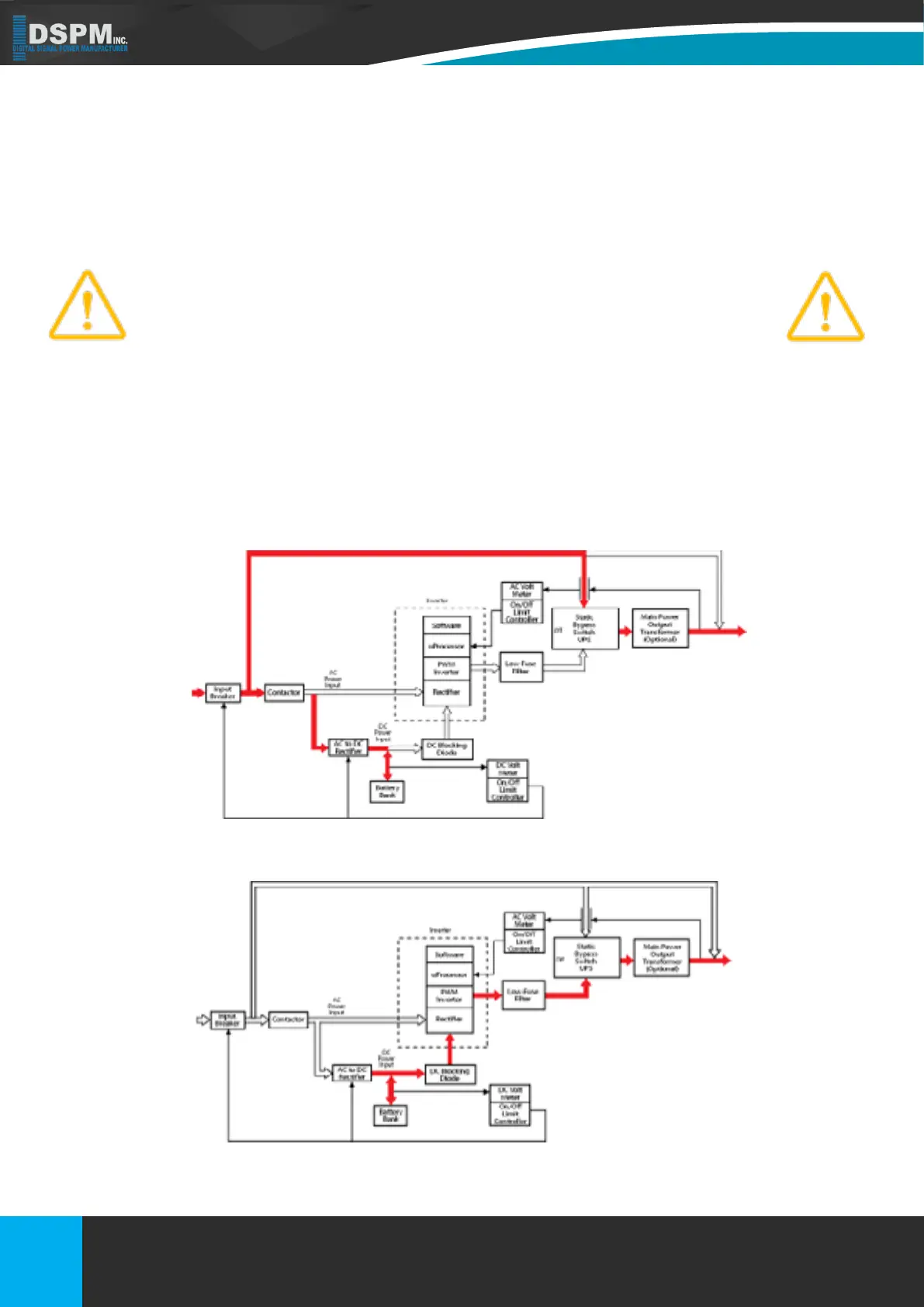
1.6.A. Normal Operation
During normal operation, the path through the inverter is used to power the load. Referring to Figure1: two rectiers
convert Input AC power to DC. DC power is utilized to charge the UPS battery system
(AC to DC Rectier). The Inverter also convert AC to DC (Rectier) to be able to generate clean AC power to supply
1.6.B. MANUAL BYPASS OPERATION
Refer to Figure 2. A Manual Bypass Switch is provided as a standard feature of the DSPM’s UPS. This switch is
to bypass the inverter logic incase of failure, to enable the end user function until service can be performed. The
advantage of this form of bypass is that the input ltering is still providing protection to the critical loads on the UPS.
Figure 2 illustrates the ow diagram when the UPS has been manually bypassed.
The conversion - inversion process eliminates any voltage transients or
Figure 2 Single Line Drawing - Static Bypass Operation
Figure 3 Single Line Drawings -AC Loss/Battery Operation
Figure 3 Single Line Drawings -AC Loss/Battery Operation
Title: Micro
Doc No.: 018-1000-02
Description: Emergency Lighting Inverter User’s Manual Date: 07/26/2016
Rev: NR
1.877.DSPM.POWERPhone : 1.877.377.6769-
909.930.3335Fax:
www.dspmanufacturing.com
Website:
techsupport@dspmanufacturing.com
E-Mail:
16
Title: Three Phase 208 or 208Y/120Vac
Doc No.: 018-6000-00
Description: Emergency Lighting Inverter User’s Manual
Rev: NR
Date: 08/12/2022
Phone :
Website:
E-Mail:
Fax:
1.877.DSPM.POWER-1.877.377.6769
1.877.DSPM.POWER-1.877.377.6769
www.dspmanufacturing.com
techsupport@dspmanufacturing.com