EasyManua.ls Logo

Dual 506 - Cartridge Mounting (1;2 Inch); Anti-Skating Force Adjustment; Tone Arm Lift Operation; Lift Height Adjustment

Dual 506
12 pages
Print Icon
To Next Page IconTo Next Page
To Previous Page IconTo Previous Page
Loading...
Fig.
8
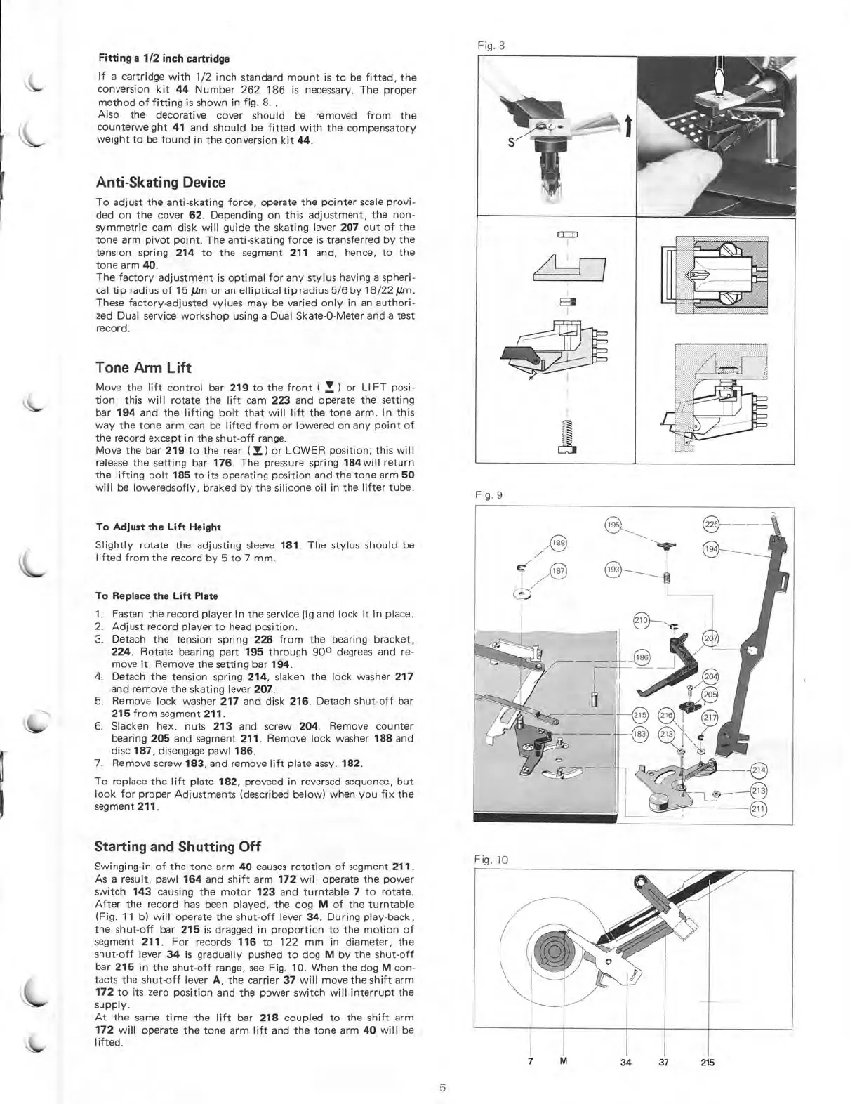
Fitting
a
1/2
inch
cartridge
If
a
cartridge
with
1/2
inch
standard
mount
is
to
be
fitted,
the
conversion
kit
44
Number
262
186
is
necessary.
The
proper
method
of
fitting
is
shown
in
fig.
8.
.
Also
the
decorative
cover
should
be
removed
from
the
counterweight
41
and
should
be
fitted
with
the
compensatory
weight
to
be
found
in
the
conversion
kit
44.
Anti-Skating
Device
To
adjust
the
anti-skating
force,
operate
the
pointer
scale
provi-
ded
on
the
cover
62.
Depending
on
this
adjustment,
the
non-
symmetric
cam
disk
will
guide
the
skating
lever
207
out
of
the
tone
arm
pivot
point.
The
anti-skating
force
is
transferred
by
the
tension
spring
214
to
the
segment
211
and,
hence,
to
the
tone
arm
40.
The
factory
adjustment
is
optimal
for
any
stylus
having
a
spheri-
cal
tip
radius
of
15
Um
or
an
elliptical
tip
radius
5/6
by
18/2211m.
These
factory-adjusted
vylues
may
be
varied
only
in
an
authori-
zed
Dual
service
workshop
using
a
Dual
Skate
-0
-Meter
and
a
test
record.
Tone
Arm
Lift
Move
the
lift
control
bar
219
to
the
front
(
V
)
or
LIFT
posi-
tion;
this
will
rotate
the
lift
cam
223
and
operate
the
setting
bar
194
and
the
lifting
bolt
that
will
lift
the
tone
arm.
In
this
way
the
tone
arm
can
be
lifted
from
or
lowered
on
any
point
of
the
record
except
in
the
shut-off
range.
Move
the
bar
219
to
the
rear
(
1)
or
LOWER
position;
this
will
release
the
setting
bar
176.
The
pressure
spring
184wi11
return
the
lifting
bolt
185
to
its
operating
position
and
the
tone
arm
50
will
be
loweredsofly,
braked
by
the
silicone
oil
in
the
lifter
tube.
To
Adjust
the
Lift
Height
Slightly
rotate
the
adjusting
sleeve
181.
The
stylus
should
be
lifted
from
the
record
by
5
to
7
mm.
To
Replace
the
Lift
Plato
1.
Fasten
the
record
player
in
the
service
jig
and
lock
lt
in
place.
2.
Adjust
record
player
to
head
position.
3.
Detach
the
tension
spring
226
from
the
bearing
bracket,
224.
Rotate
bearing
part
195
through
90
0
degrees
and
re-
move
it.
Remove
the
setting
bar
194.
4.
Detach
the
tension
spring
214,
slaken
the
lock
washer
217
and
remove
the
skating
lever
207.
5.
Remove
lock
washer
217
and
disk
216.
Detach
shut-off
bar
215
from
segment
211.
6.
Slacken
hex.
nuts
213
.and
screw
204.
Remove
counter
bearing
205
and
segment
211.
Remove
lock
washer
188
and
disc
187,
disengage
pawl
186.
7.
Remove
screw
183,
and
remove
lift
plate
assy.
182.
To
replace
the
lift
plate
182,
proveed
in
reversed
sequence,
but
look
for
proper
Adjustments
(described
below)
when
you
fix
the
segment
211.
Starting
and
Shutting
Off
Swinging-in
of
the
tone
arm
40
causes
rotation
of
segment
211.
As
a
result,
pawl
164
and
shift
arm
172
will
operate
the
power
switch
143
causing
the
motor
123
and
turntable
7
to
rotate.
After
the
record
has
been
played,
the
dog
M
of
the
turntable
(Fig.
11
b)
will
operate
the
shut-off
lever
34.
During
play-back,
the
shut-off
bar
215
is
dragged
in
proportion
to
the
motion
of
segment
211.
For
records
116
to
122
mm
in
diameter,
the
shut-off
lever
34
is
gradually
pushed
to
dog
M
by
the
shut-off
bar
215
in
the
shut-off
range,
see
Fig.
10.
When
the
dog
M
con-
tacts
the
shut-off
lever
A,
the
c,arrier
37
will
move
the
shift
arm
172
to
its
zero
position
and
the
power
switch
will
interrupt
the
supply.
At
the
same
time
the
lift
bar
218
coupled
to
the
shift
arm
172
will
operate
the
tone
arm
lift
and
the
tone
arm
40
will
be
lifted.
1
I
1
1
Fig.
9
Fig.
10
5