EasyManua.ls Logo

Dual CV 1460 Service Manual

Dual CV 1460
11 pages
To Next Page IconTo Next Page
Page #1 background imageLoading...
Page #1 background image
Blockschaltbild
PHO
N
0
TUNER
MC/MM
TAPE
-1
P.
B
TAPE
-1
REC
INPUT
SELECTOR
4-
-14-
4-
i4-
_
1
L.
-J
--f
R
IAA
TAPE-
2
P.8
TAPE
-2
REC
TAPE
(3)
COPY
MONITOR
T
-
1
7
4
:1
I
L
MON
ITER
Dual
CV
1460
Service
-Anleitung
Service
Manual
Instructions
de
Service
SUBSON
IC
FILTER
22V
E
-
20
V
BALANCE
VOLUME
LOUDNESS
REGULATOR
55V
55V
BASS
TREBLE
FUSE
AC33V
FUSE
El
FUSE
SPEAKER
I
SPE
AKER
2
PHONES
POWER
METER
,
POWER
SW
r
FUSE
50/60Hz
AC
230V
Dual
GmbH
Postfach
1144
7742
St.
Georgen/Schwarzwald
920
831
6/1283
Copyright
by
Dual
Download from www.dual.de
Not for commercial use
Question and Answer IconNeed help?

Do you have a question about the Dual CV 1460 and is the answer not in the manual?

Dual CV 1460 Specifications

General IconGeneral
BrandDual
ModelCV 1460
CategoryAmplifier
LanguageEnglish

Summary

Blockschaltbild

Technische Daten

Rated output (DIN / 8 Ω)

Specifies music power, continuous RMS power, and IHF power details.

Harmonic distorsion

Details harmonic distortion at 2 x 70 watts, 1000 Hz.

Signal-to-Noise ratio

Measures peak value via extraneous voltage filter (DIN 45 405).

Fuses

Specifies fuse ratings for different voltage inputs (115V, 230V).

Schaltbild

Phono Input Circuit

Detailed schematic for the phono input stage, including MC/MM switching.

Tuner and Tape Input Circuits

Schematic sections for tuner and tape inputs, including tape copy.

Tone Control and Volume Circuitry

Circuitry for balance, volume, tone controls, and loudness.

Power Supply and Regulator

Circuitry for power regulation and supply voltages (-20V, +19.5V).

Explosionszeichnung

Pre-amplifier and Tone Control Stage

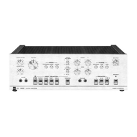
Exploded view of the pre-amplifier section with tone and balance controls.

Power Amplifier Stages

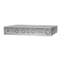
Exploded view of the power amplifier components and heatsinks.

Power Supply Unit

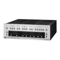
Exploded view of the power supply transformer and associated components.

Front Panel Assembly

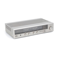
Exploded view of the front panel controls, display, and housing.

Ersatzteile

Transistors and Diodes

List of transistors (e.g., 2SA, 2SC, 2SK series) and diodes used in the unit.

Integrated Circuits (ICs)

Specific ICs used, such as TA 7318 P, RC 4558, and NJM 4558.

Passive Components

List of resistors (VR potentiometers) and capacitors.

Connectors and Switches

Details on RCA jacks, DIN sockets, speaker terminals, and switches.

Abgleichanleitung

Quiescent Current Adjustment

Procedure for adjusting quiescent current using a DC voltmeter.

Power Meter Calibration

Instructions for calibrating the power meter using an AF generator.

Output Level Adjustment

Procedure for setting output levels for tuner and speaker outputs.

Alignment Positions Diagram

Diagram showing adjustment points (VRs) and test points (TPs) on the PCB.