4. Electrical Installation
Electrical connection [11]
Electrical fittings, cables and diodes [12]
Grounding and lightning protection [14]
Indirect lightning strike [14]
4.1. Electrical connection
The nominal electrical parameters Icc, Vco and Pmax of the modules are determined under standard test con-
ditions STC (standard testing condition): illumination of 1000 W/m² with a spectrum of 1.5 AM and a cell tem-
perature of 25°C. These values may vary from +/-3%.
NOTE
Under normal conditions, a photovoltaic module is likely to be exposed to conditions which
produce more current and / or voltage than what is measured under standard test conditions.
Therefore, the maximum values of I
CC
and V
CO
noted on the module should be multiplied
by 1.25 when determining the rated voltage of the components, the nominal current of the
conductors, the size of the fuses, and the size of the control tools connected to the PV output
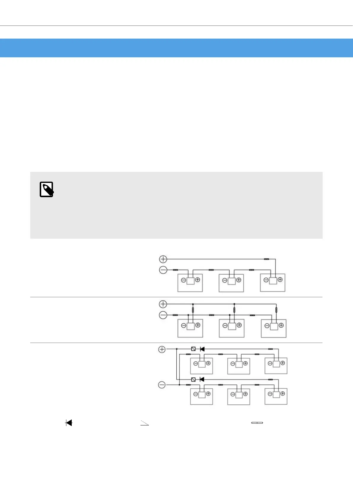
Wiring in series
Wiring in parallel
Serial / parallel wiring
Diode Overcurrent protection Connector
1. Wiring in series
To wire modules in series, the maximum number of connectable modules must be determined. For this it is
necessary to determine the maximum tension of the string. This is calculated by adding the open circuit
Installation, use, maintenance manual DualSun FLASH
11