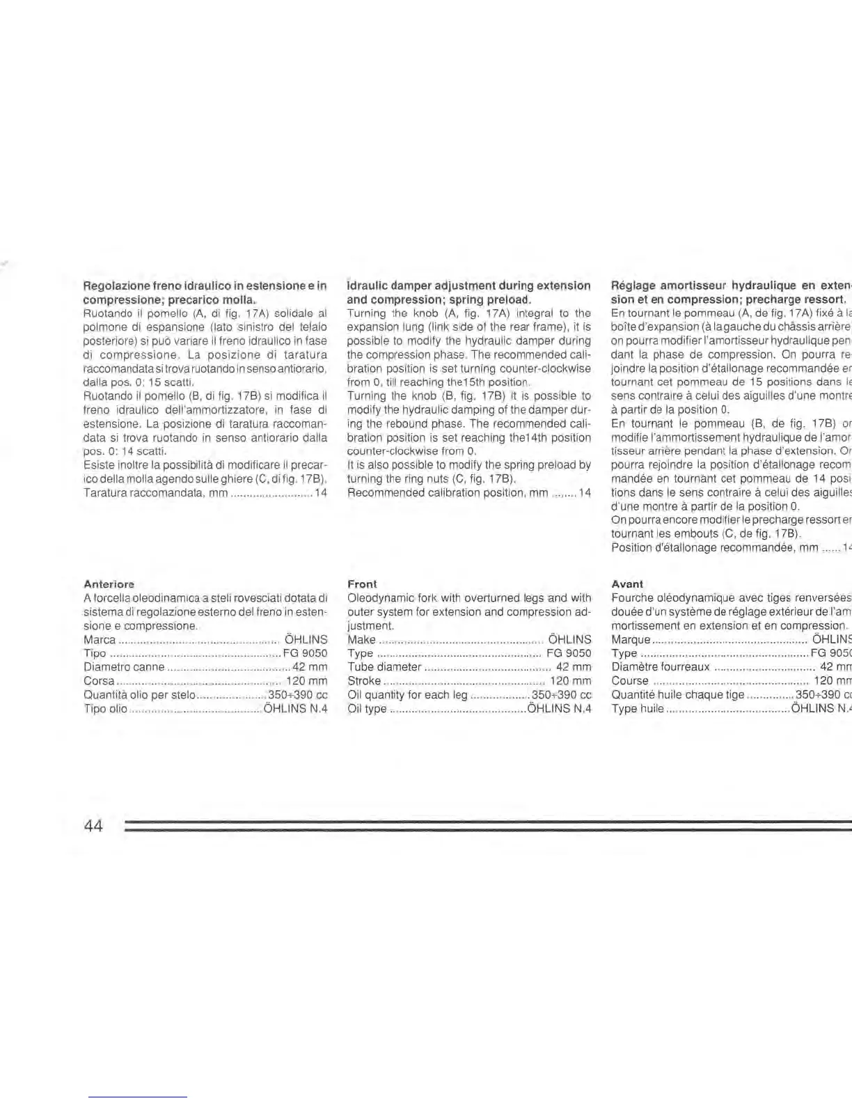
Regolazione freno idraulico in estensione e in
compressione; precarico
molla.
Ruotando
il
pomello
(A,
di
fig. 17
A)
solidale
al
polmone di espansione (Iato sinistro del telaio
posteriore)
si
pub variare
il
freno idraulico
in
fase
di
compressione.
La
posizione
di
taratura
raccomandata
si
trova ruotando
in
senso antiorario,
dalla pos.
0:
15 scatti.
Ruotando
iI
pomello (8, di fig. 178)
si
modifica
il
freno idraulico dell'ammortizzatore,
in
fase
di
estensione.
La
posizione di taratura raccoman-
data
si
trova ruotando
in
senso antiorario dalla
pos.
0:
14 scatti.
Esiste inoltre
la possibilita
di
modificare
il
precar-
ico della molla agendo sulle ghiere
(C,
di
fig. 178).
Taratura raccomandata,
mm
.........
..
....
......
...
..
14
Anteriore
A forcella oleodinamica a steli rovesciati dotata
di
sistema di regolazione esterno del freno
in
esten-
sione e compressione.
Marca
...
.
...
......
..
... ...
.............................. OHLlNS
Tipo ......................................................
FG
9050
Diametro canne
..
.....................................
42
mm
Corsa ..................................
..
................ 120
mm
Quantita olio per stelo ...................... 350+390 cc
Tipo
olio ............................
..
..
. ...... OHLlNS N.4
44
Idraulic damper adjustment during extension
and compression; spring
preload.
Turning the knob
(A,
fig. 17A) integral
to
the
expansion
lung (link side of the rear frame),
it
is
possible
to
modify the hydraulic damper during
the compression phase. The recommended
cali-
bration position
is
set turning counter-clockwise
from
0, till reaching the15th position.
Turning the knob (8, fig. 178) it
is
possible to
modify the hydraulic damping of the damper
dur-
ing the rebound phase. The recommended cali-
bration position
is
set reaching the14th position
counter-clockwise from
O.
It
is also possible to modify the spring preload by
turning the ring nuts
(C,
fig. 178).
Recommended calibration position,
mm
........ 14
Front
Oleodynamic fork with overturned legs and with
outer system for extension and compression
ad-
justment.
Make ................................
..
.................. OHLlNS
Type ........................
..
.......
..
..
........
..
.....
FG
9050
Tube diameter ........................................ 42
mm
Stroke ................................................... 120
mm
Oil quantity for each leg ................... 350+390 cc
Oil type ........................................... OHLlNS
NA
Reglage amortisseur hydraulique en exten·
sion et en compression; precharge ressort.
En
tournant
le
pommeau
(A,
de fig. 17A) fixe a
la
boite d'expansion (a la gauche du chassis arriere)
on
pourra modifier I'amortisseur hydraulique pen·
dant la phase de compression. On pourra
re·
joindre la position d'etallonage recommandee
en
tournant cet pommeau de 15 positions dans
le
sens contraire a celui des aiguilles d'une montre
a partir de la position
O.
En
tournant
le
pommeau (8, de fig. 178) on
modifie I'ammortissement hydraulique de
I'amor·
tisseur arriere pendant la phase d'extension. On
pourra rejoindre la position d'etallonage recom·
mandee
en
tournant cet pommeau de 14 posi·
tions dans
le
sens contraire a celui des aiguilles
d'une montre a partir de
la
position
O.
On pourra encore modifier
le
precharge ressort
en
tournant les embouts
(C,
de fig. 178).
Position d'etallonage recommandee,
mm
......
14
Avant
Fourche oleodynamique avec tiges renversees,
douee d'un systeme de reglage exterieur de I'am-
mortissement
en
extension et en compression.
Marque .................................................
OHLlNS
Type .....................................................
FG
9050
Diametre fourreaux ................................ 42
mm
Course ....
.....
....................................... 120
mm
Quantite huile chaque tige ............... 350+390
cc
Type huile ....................................... OHLlNS N.4
 Loading...