www.factorybuysdirect.com
17200245-01G
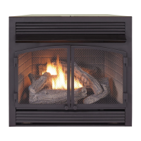
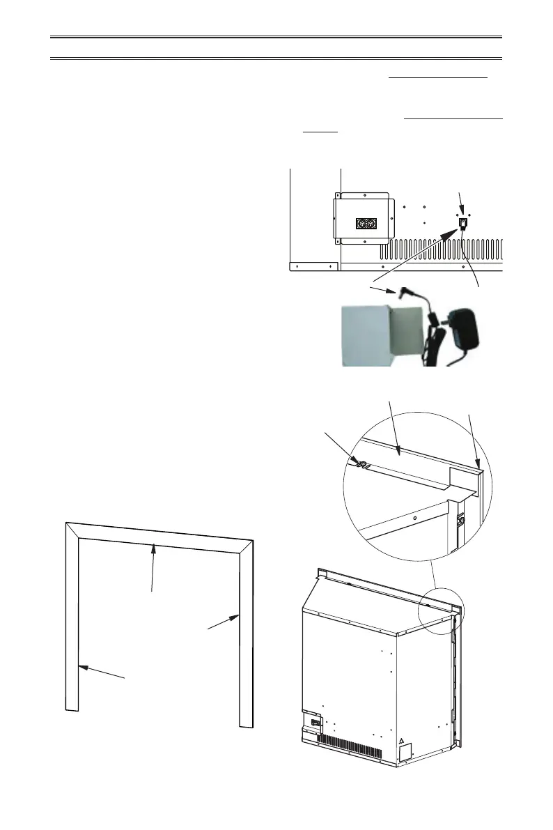
Top Trim Piece
Left Trim Piece
Right Trim Piece
Figure 18 - Decorative Trim
Figure 19 - Installing Decorative Trim
INSTALLATION
4. Check all joints from equipment shuto
valve to control valve (see Figure 16 or
17, page 16). Apply a noncorrosive leak
detection uid to all joints. Bubbles form-
ing show a leak.
5. Correct all leaks at once.
INSTALLATION FOR DECORATIVE TRIM
6. Light heater (see Lighting Instructions on
page 20). Check all other internal joints
for leaks.
7. Turn o heater (see To Turn O Gas Ap-
pliance, page 21).
1. Identify left, right and top decorative trim
pieces (see Figure 18).
2. Starting with the left and right side trim
pieces, snap the screw clips over the
shoulder screws provided on the replace.
Snap the top trim on last (see Figure 19).
Note: The shoulder screws do not need
to be tightened down to hold the trim in
place.
Shoulder
Screw
Top Decorative
Trim
Left/Right
Decorative Trim
CONNECTING ELECTRICAL SUPPLY
This replace insert requires an 120V
electrical output within 4 feet of the
unit. Extension cords may be used.
The remote receiver requires 4 AA bat-
teries. This powers the heater in case
of an electrical power outage.
1. Locate 6V DC adapter.
2. Plug Connector End of Adapter into the
Power Change Supply on the back of the
heater.
3. Plug adapter into 120V electrical outlet.
Power Change
Supply
Connector End
of Adapter